


7
W415-0469 / A / 01.04.05
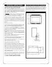
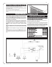
This fireplace requires a 15 amp, 120 volt and 60 hz
circuit. The fireplace should be on its own circuit. If
there are other appliances on the same circuit, this may
cause the circuit breaker or fuse to blow when the fire-
place heater is in operation.
The unit comes with a 6' electrical cord, exiting the bot-
tom right side. Plan your installation to avoid the use of
an extension cord. If you require an extension cord, it
must be at least 16 awg wire and be rated for 2025
watts.
Electrical outlet wires must comply with local building
codes to reduce the risk of fire, electrical shock and
injury.
Do NOT use the fireplace if any part has been under
water.
Call a qualified service technician IMMEDIATELY to have
the fireplace inspected for damage to the electrical cir-
cuit.
If it is necessary to hard wire this fireplace, a qualifiedIf it is necessary to hard wire this fireplace, a qualified
If it is necessary to hard wire this fireplace, a qualifiedIf it is necessary to hard wire this fireplace, a qualified
If it is necessary to hard wire this fireplace, a qualified
electrician may remove the cord connection, and wireelectrician may remove the cord connection, and wire
electrician may remove the cord connection, and wireelectrician may remove the cord connection, and wire
electrician may remove the cord connection, and wire
this unit directly to the house hold wiring.this unit directly to the house hold wiring.
this unit directly to the house hold wiring.this unit directly to the house hold wiring.
this unit directly to the house hold wiring.
Permanently framing the fireplace with an enclosure, re-
quires the fireplace to be hardwired.
This fireplace must be electrically connected and grounded
in accordance with local codes, if hard wired. In the ab-
sence of local codes, use the current CSA C22.1 CANADIAN
ELECTRICAL CODE in Canada or the ANSI/NFPA 70-1996
NATIONAL ELECTRICAL CODE in the United States.
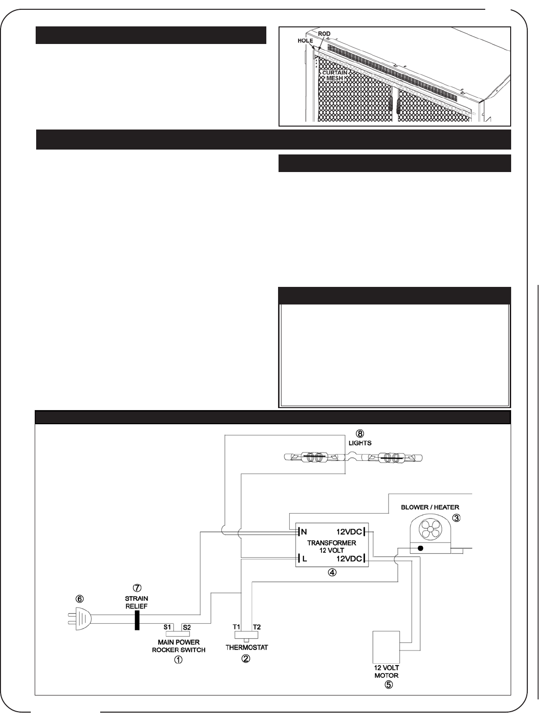
ELECTRICAL CONNECTION
HARD WIRING CONNECTION
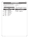
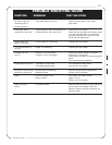
ELECTRICAL DIAGRAM LEGEND
1.1.
1.1.
1.
Power (Rocker Switch)Power (Rocker Switch)
Power (Rocker Switch)Power (Rocker Switch)
Power (Rocker Switch)
W660-0023W660-0023
W660-0023W660-0023
W660-0023
2.2.
2.2.
2.
Thermostat SwitchThermostat Switch
Thermostat SwitchThermostat Switch
Thermostat Switch
W660-0040W660-0040
W660-0040W660-0040
W660-0040
3.3.
3.3.
3.
Fan / Heater AssemblyFan / Heater Assembly
Fan / Heater AssemblyFan / Heater Assembly
Fan / Heater Assembly
W062-0019W062-0019
W062-0019W062-0019
W062-0019
4.4.
4.4.
4.
Main Circuit BoardMain Circuit Board
Main Circuit BoardMain Circuit Board
Main Circuit Board
W707-0003W707-0003
W707-0003W707-0003
W707-0003
5.5.
5.5.
5.
DC Motor (flame effect)DC Motor (flame effect)
DC Motor (flame effect)DC Motor (flame effect)
DC Motor (flame effect)
W435-0006W435-0006
W435-0006W435-0006
W435-0006
6.6.
6.6.
6.
Main Power CordMain Power Cord
Main Power CordMain Power Cord
Main Power Cord
W750-0143W750-0143
W750-0143W750-0143
W750-0143
7.7.
7.7.
7.
Strain ReliefStrain Relief
Strain ReliefStrain Relief
Strain Relief
W105-0002W105-0002
W105-0002W105-0002
W105-0002
8.8.
8.8.
8.
Flame Effect LightFlame Effect Light
Flame Effect LightFlame Effect Light
Flame Effect Light
W750-0126W750-0126
W750-0126W750-0126
W750-0126
(two light sockets-(two light sockets-
(two light sockets-(two light sockets-
(two light sockets-
75quartz watts max75quartz watts max
75quartz watts max75quartz watts max
75quartz watts max
))
))
)
9.9.
9.9.
9.
Nylon Cable TieNylon Cable Tie
Nylon Cable TieNylon Cable Tie
Nylon Cable Tie
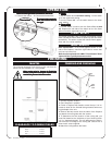
Electric Diagram
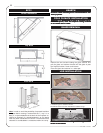
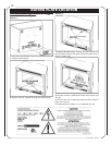
OPTIONAL SCREEN INSTALLATION
1. Bunch the curtain mesh in the middle of the rod.
2. Insert one end of the rod through the hole indicated in the side
of the firebox frame.
3. The rod will need to be bowed in the middle in order to insert the
other end of the rod into the opposite hole.
4. Tuck the bottom of the curtain mesh behind the front lip of the
retainer.