


20
W415-0299 / C / 03.12.03
For safe and proper operation of the fireplace, follow
the venting instructions exactly.
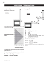
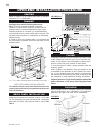
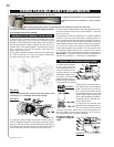
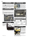
1. Stretch the 5" diameter aluminum flexible liner to the
required length taking into account the additional length
needed for the finished wall surface. Apply a heavy bead of
the high temperature sealant, supplied with the unit, to the
inside of the 5" liner approximately 1" from the end. Slip the
liner a minimum of 2" over the fireplace vent collar and
secure with 3 #8 screws.
2. Using the 8" diameter flexible aluminum liner, apply seal-
ant, slide a minimum of 2" over the fireplace combustion
air collar and secure with 3 #8 screws.
The air teminal may be recessed into the exterior wall
or siding by 1½", the depth of the return flange.
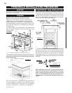
3. Insert the liners through the firestop. Position and se-
cure the fireplace using the nailing tabs (2 per side) and/or
secure to the floor using screws inserted through the two
¼" diameter holes in the front left and right corners of the
base. The liners should be flush with the exterior wall.
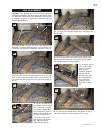
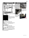
5. From outside, apply a bead of the high temperature seal-
ant to the inside of both liners, approximately 1" from the
end of each liner.
5. Holding the air terminal (lettering in an upright, readable
position), insert into both liners with a twisting motion to
ensure that both the terminal sleeves engage into the lin-
ers / sealant. Secure the terminal to the exterior wall and
make weather tight by sealing with caulking (not supplied).
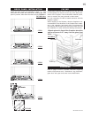
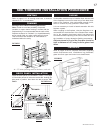
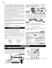
6. If more liner needs to be used to reach the fireplace,
couple them together as illustrated. The vent system must
be supported approximately every 3 feet for both vertical
and horizontal runs. Use Napoleon support ring assembly
W010-0380 or equivalent noncombustible strapping to
maintain the minimum 1" clearance to combustibles.
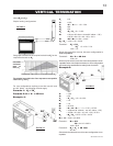
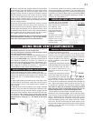
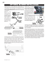
1. Fasten the roof support
to the roof using the
screws provided. The roof
support is optional. In this
case the venting is to be
adequately supported us-
ing either an alternate
method suitable to the au-
thority having jurisdiction
or the optional roof support.
2. Stretch the 5" diameter alumi-
num flexible liner to the required
length. Slip the liner a minimum
of 2" over the inner sleeve of the
air terminal and secure with 3 #8
screws. Seal using a heavy bead
of the high temperature sealant.
3. Repeat using 8" diameter alu-
minum flexible liner.
5. Thread the air terminal pipe
assembly down through the roof.
The air terminal must be located
vertically and plumb. Attach the air terminal assembly to
the roof support, ensuring that a minimum 16" of air termi-
nal will penetrate the roof when fastened.
DO NOT CLAMP THE
FLEXIBLE ALUMINUM
LINER.
FIGURE 38
FIGURE 36
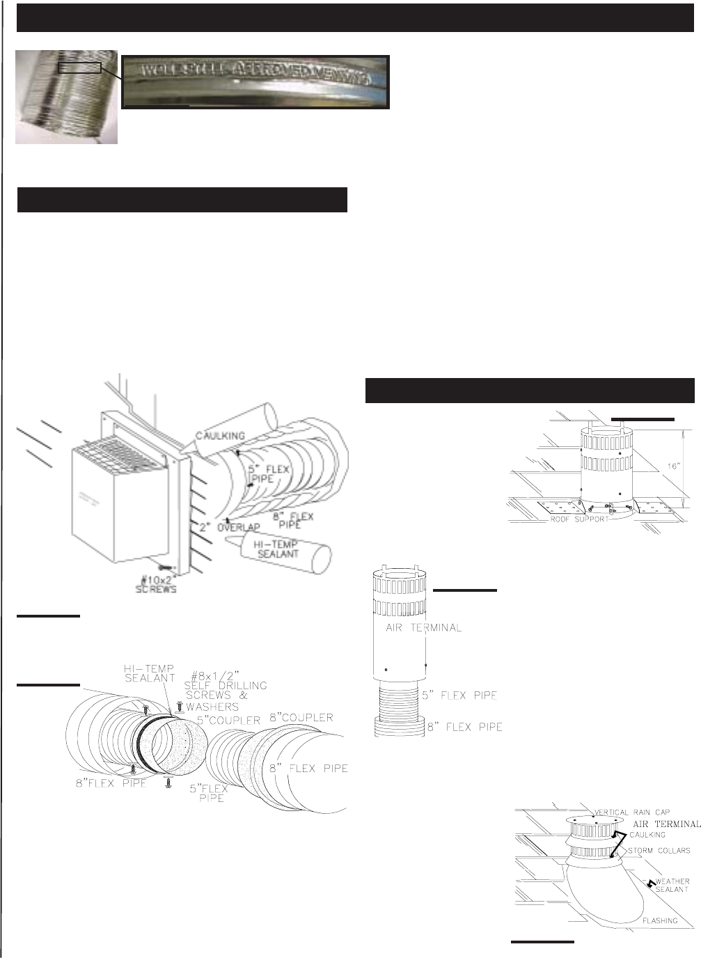
USING FLEXIBLE VENT COMPONENTS
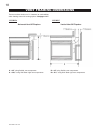
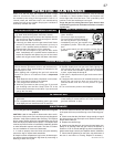
Use only approved aluminum flexible liner kits marked:
"Wolf Steel Approved Venting" as identified by the stamp only on the 8” outer liner.
For optimum performance, it is recommended that
horizontal runs have a minimum ¼ inch rise per
foot .
FIGURE 33
HORIZONTAL AIR TERMINAL INSTALLATION
VERTICAL AIR TERMINAL INSTALLATION
FIGURE 34
FIGURE 35
FIGURE 37