


9
W415-0098 / A / 08.07.03
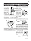
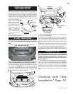
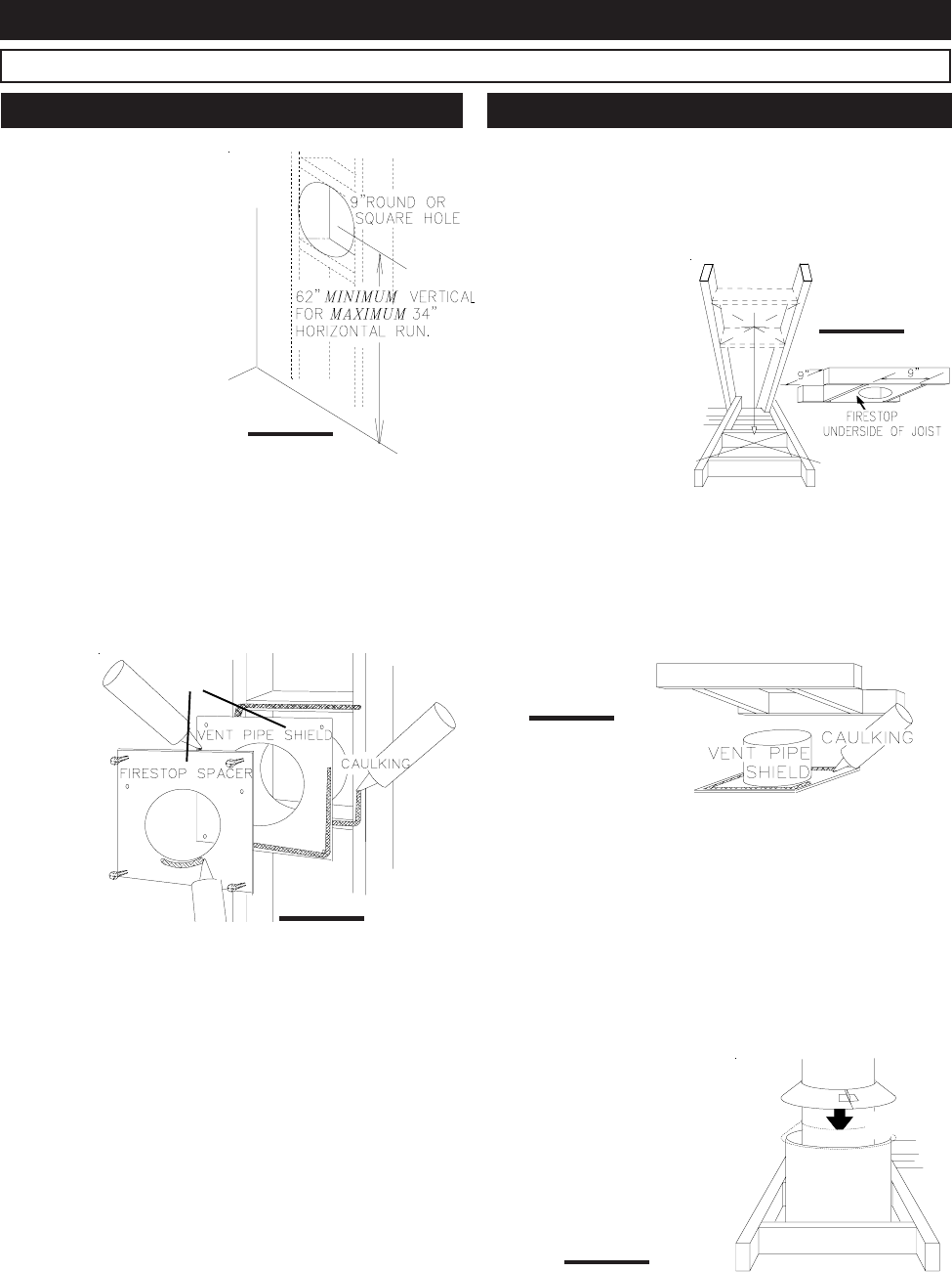
This application occurs
when venting through an ex-
terior wall. FIGURES
5, 6, & 13. Having deter-
mined the air terminal loca-
tion, cut and frame a hole in
an exterior wall with a mini-
mum square or round open-
ing of 9". (As an alternative
to framing, a vent pipe
shield may be installed, en-
suring a 1" clearance to
combustibles. See
Figure 12.)
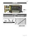
THE STOVE PIPE MUST RISE ¼" PER FOOT OF RUN.
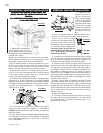
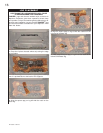
1. Mark and cut the vent pipe shield to the determined
depth of the combustible wall. Apply a bead of caulking (not
supplied) to the framework or to the shield plate (in the
case of a finished wall) and secure the shield through the
opening to the interior wall. The final location of the vent
pipe shield should maintain the required clearance to the
7" vent pipe. Do not fill this cavity with any type of material.
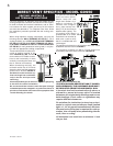
This application occurs when venting through a roof.
FIGURE 4. Installation kits for various roof pitches are avail-
able from your Napoleon dealer. See Accessories to order
the specific kit required.
1. Determine the air ter-
minal location and move
the stove into position.
Cut and frame 9 inch
openings in the ceiling
and the roof to provide the
minimum 1 inch clear-
ance between the stove
pipe and any combustible
material. Try to center the
exhaust pipe location
midway between two joist
to prevent having to cut
them. Use a plumb bob
to line up the center of the
openings.
Do not fill this space with any type of material.
A vent pipe shield will prevent any materials such as insu-
lation, from filling up the 1" air space around the pipe.
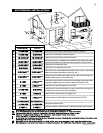
FIGURE 16. Nail headers between the joist for extra sup-
port.
FIGURE 14
FIGURE 13
OR
FOR SAFE AND PROPER OPERATION OF THE STOVE, FOLLOW THE VENTING INSTRUCTIONS EXACTLY.
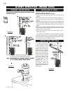
Apply a bead of caulking all around and place a firestop
spacer over the vent shield to restrict cold air from being
drawn into the room or around the stove. Ensure that both
spacer and shield maintain the required clearance to com-
bustibles. Once the vent pipe is installed in its final posi-
tion, apply sealant between the pipe and the firestop spacer.
2. Apply a bead of caulking (not supplied) to the frame-
work or to the Wolf Steel vent pipe shield plate or equivalent
(in the case of a finished ceiling), and secure over the open-
ing in the ceiling. FIGURE 15. A firestop must be placed on
the bottom of each framed opening in a roof or ceiling that
the venting system passes through. FIGURE 14. Apply a
bead of caulking all around and place a firestop spacer
over the vent shield to restrict cold air from being drawn into
the room or around the stove. Ensure that both spacer and
shield maintain the required clearance to combustibles.
Once the vent pipe is installed in its final position, apply
sealant between the pipe and the firestop spacer.
3. In the attic, after the pipe
has been installed, slide the
vent pipe collar down to cover up
the open end of the shield and
tighten. This will prevent any ma-
terials, such as insulation, from
filling up the 1" air space around
the pipe.
FIGURE 15
VENT PIPE
SHIELD
VEN
T
PIP
E
COLLA
R
FIGURE 16
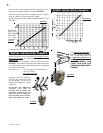
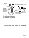
WALL AND CEILING PROTECTION
FIGURE 12
HORIZONTAL INSTALLATION VERTICAL INSTALLATION