


12
W415-0098 / A / 08.07.03
Follow the instructions for "Wall and Ceiling Protection".
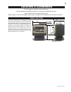
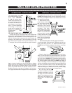
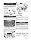
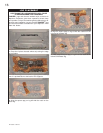
ADAPTER INSTALLATION FIGURE 27
1. Remove the spill switch bracket from the rear of the
adapter.
2. Gently pull the two wire terminals (located inside the 7"
flue collar at the top of the stove) out approximately 8
inches.
3. Bring the wires through the lower hole in the adapter and
out the spill switch opening. To pass the wires through the
hole more easily, temporarily tape the two terminals to-
gether.
4. With the spill switch opening aligned to the back of the
stove, take hold of the adaptor base and push the crimped
edge into the stove flue collar.
5. Connect the wire terminals to the spill switch and re-
secure the bracket.
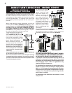
For aesthetics, the adapter has been designed to accept
a standard matte black 7" stove pipe and the Napoleon
decorative brass band (standard with the GS150KT). Both
are available from your Napoleon dealer.
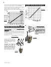
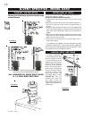
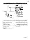
For ease of assembly, a
7" telescoping stove pipe
may be installed over the
4" vent connection of the
adapter. Add vent sections,
twist locking (clockwise)
securely, to the required
height. The vent should ex-
tend, at least, 3 feet above
its point of contact with the
roof and, at least, 2 feet
higher than any wall, roof
or building within 10 feet.
FIGURE 28. (This is a
guideline only; local vent-
ing codes should be
followed which may differ in
height and clearance re-
quirements.)
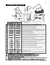
Three types of chimney systems may be used
with this stove:
A CHIMNEY VENTING THIS STOVE SHALL NOT VENT
ANY SOLID FUEL BURNING APPLIANCE.
ALL HORIZONTAL RUNS MUST HAVE
A 1/4 INCH RISE PER FOOT.
FIGURE 26
SWITCH
SPILL
ADAPTER
FIGURE 27
FIGURE 28
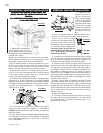
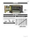
B-VENT SPECIFICS - MODEL GS50
CHIMNEY INSTALLATION INSTALLING 'B' VENT:
ADDING VENT SECTIONS