


‘‘1’’ in two consecutive locations.
TAMPERTAMPER
If the cover is removed, the keypad sounder will pulse and
the display will indicate a zone-module tamper condition
along with the module number. Press [RESET] to silence the
sounder.
LOOP RESPONSELOOP RESPONSE
Loop response times for Zones 1 through 8 are pro-
grammed in the control panel. Normal loop response for
all expansion zones is 750mS. To reduce the response time
of an expansion zone to 50mS, cut the respective resistor
at the upper-left corner of the board. Refer to the Wiring
Diagram.
STATUS LEDSTATUS LED
The Status LED displays the condition of the zone mod-
ule. The LED will blink every few seconds to indicate that
each 4-zone group is operating normally. The LED in the
4-zone module will blink once; the LED in the 8-zone
module will blink once for the first group, then double-blink
shortly thereafter for the second. See TROUBLESHOOT-
ING for other indications.
PGM TERMINALPGM TERMINAL
The PGM terminal (Terminal 6) will go low when the area
is armed. This terminal may be used to light an LED or trip
auxiliary equipment. Note:Note: This terminal is programmed in
the control panel; it may be selected to trip when any one
area is armed (not necessarily its own). Refer to the instal-
lation instructions for the control panel for programmable
options.
4Z/8Z ZONE JUMPER4Z/8Z ZONE JUMPER
To convert an 8-zone module for use with only 4-zones,
remove the jumper just below the large microprocessor IC
on the circuit board.
TROUBLESHOOTINGTROUBLESHOOTING
• A steady Status LED is most likely caused by loss of
data reception from the control panel at the module’s
Terminal 3.
• No illumination is most likely due to a loss of power at
Terminals 1 and/or 2.
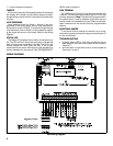
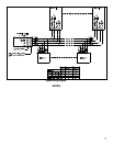
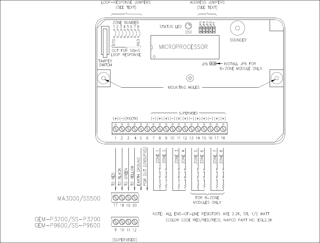
WIRING DIAGRAMSWIRING DIAGRAMS
Zone Wiring Diagram.Zone Wiring Diagram.
22