


INTRODUCTION
The GEM-RP3DGTL is a dual 7-segment digital keypad that is compatible with the NAPCO GEM-Series GEM-P816,
P1632, P3200 & P9600 control-panels. Refer to User Guide OI249 for operation instructions. While the GEM-RP3DGTL
may be used to fully program the control, the GEM-RP1CAe2 keypad provides the optimum in ease of keypad
programming.
SPECIFICATIONS
Operating Voltage: 12 V DC (supplied by panel)
Current Drain:50 mA Standby
Dimensions: 4 3/8” x 5 7/8” x 11/16”
Note: Subtract keypad current from combined auxiliary current of the control panel.
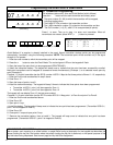
MOUNTING THE KEYPAD
A keypad should be located near each exit/entry door. To open the case, insert a screwdriver into either slot at the bottom
and push up with a slight twisting motion to release the retainer tab. Repeat for the other slot. Pull out at the bottom and lift
off the two hooks at the top.
The GEM-RP3DGTL features a handy pull-up reference label. (This label must be used in UL installations.) Before
mounting the keypad onto the wall, push the Sliding Label Plate (with label and felt backing affixed and handle facing
forward) down the guides at the rear of the keypad until it snaps into place. Once installed, the Sliding Label Plate cannot
be removed without first removing the keypad from the wall. Note: The keypad fire and panic keys should not be
considered a substitute for a listed manual initiating device, such as a pull box.
If installing onto a double-gang box, insert mounting screws through the two vertical elongated holes on the left side of the
case and into the box. If the box is visible when viewed from the front, adjust the keypad vertically and tighten the screws.
Then, using hardware suitable for the mounting surface, add one or two screws at the right side of the keypad case directly
into the wall to ensure a secure installation. Note: Do not over tighten the screws! Uneven walls may cause the keypad
case to distort.
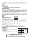
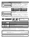
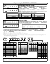
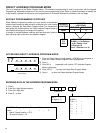
WIRING
Connect the keypad wires to the control panel
terminals shown in the table at the right.
Caution: Do not run keypad wiring with loop wiring.
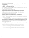
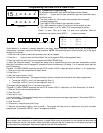
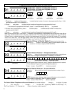
KEYPAD CONFIGURATION
Up to 7 GEM-RP3DGTL keypads may be connected to
the control panel (Keypads 1–7). Each must be config- ured for a keypad address. In addition,
the keypad may be configured to disable touchpad backlight and entry sounder. Keypads are configured by the proper
selection of jumpers. Refer to the label on the keypad circuit board for jumper locations and a summary of settings.
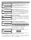
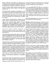
KEYPAD ADDRESS
If more than one keypad is installed:
• Each must be assigned a unique address (that is, no two keypads may be numbered alike).
• Keypads must be addressed consecutively (that is, missing numbers are not permitted).
• Only Keypad No. 1 may be used for programming. (However, for ease of programming, it is recommended that a GEM-RP1CA/
RP1CAe/RP1CAe2 be selected as Keypad #1.)
• Assign the keypad address number by selecting Jumpers J1–3 in accordance with the table below.
*Note: (1) Keypads are factory supplied with no jumpers installed and a as such are automatically configured as Key-
pad No. 1. (2) Only one keypad in the system may be configured as Keypad No. 1, otherwise none will function.
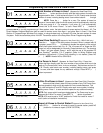
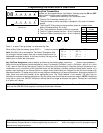
TOUCHPAD BACK LIGHT
Cut Jumper A to disable touch pad back lighting.
DISABLE SOUNDER
Cut Jumper C to disable the sounder. (Do not disable in UL applications.)
ENABLE KEYPAD TAMPER
Cut Jumper D to enable Keypad Tamper.
ENABLE TAMPER LED
Cut Jumper E to covert the Keypad CHIME LED to a SYSTEM TAMPER
LED. (Only on control panels which support system tamper)
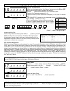
KEYPAD JUMPER SETTINGS
NUMBER
1 2 3 PARK
1 OFF or
ON
• •
2
•
ON
STORE SPARE
3 ON ON
JUMPERS
4
• •
ON
IN THIS
5 ON
•
ON
POSITION
6
•
ON ON
7 ON ON ON
COLOR TERMINAL
RED 9
BLACK 10
GREEN 11
YELLOW 12
WHITE N/O PANIC
WHITE N/O PANIC
For Sales and Repairs, call toll free: (800) 645-9445
For direct line to Technical Service, call toll free: (800) 645-9440
Internet: http://www.napcosecurity.com
* Cut and insulate 2 white wires if not used.
3