


12
34
Caution
l
d
i
d
a
Multitec
21
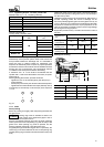
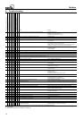
7.4.1 Tightening torques - Tie bolts, part No. 905
Material codes 10, 11, 12, 13 (casing: cast iron)
Pump size
Tightening torque Nm
Multitec 32 85
Multitec 50 140
Multitec 65 250
Multitec 100 395
Multitec 125 600
Multitec 150 700
Material code 20 to 30
(Casing: steel or stainless steel)
Pump size
Operating pressure
(bar)
Tightening torque
Nm
Multitec 32 150
Multitec 50 240
Multitec 65
All
430
Multitec 100
A
l
l
680
Multitec 125 1370
M
u
l
t
i
t
e
c
1
5
0
≤ 40
1500
M
u
l
t
i
tec 150
> 40 2000
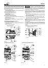
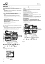
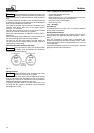
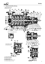
7.4.2 Reassembly of hydraulic system
Reassembly of the hydraulic system starts at the suction end
and proceeds towards the discharge end. It is advisable to
place the pump in vertical position for reassembly. The
sequence of reassembly does not pose any special problems
and shall be realized in accordance with the detailed sectional
drawing and list of components. The components shall be
re-installed in the same place as before dismantling.
A clearance of 0.7 to 1.2 mm shall be set between the last
impeller 230.1 or 230.3 and the balance drum 59-4 (or spacer
sleeve 525.4).
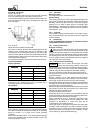
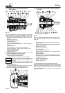
When tightening the tie bolts, proceed as follows:
- Tighten the nuts of tie bolts 905 gently, with the pump in
vertical position.
- Setthe pumphorizontally ontoitsfeet onthe assemblytable.
- Tightenthe nuts oftie bolts 905in twosteps (firststep:50%of
nominal torque, second step: nominal torque) in the sequence
1.4.2.3.
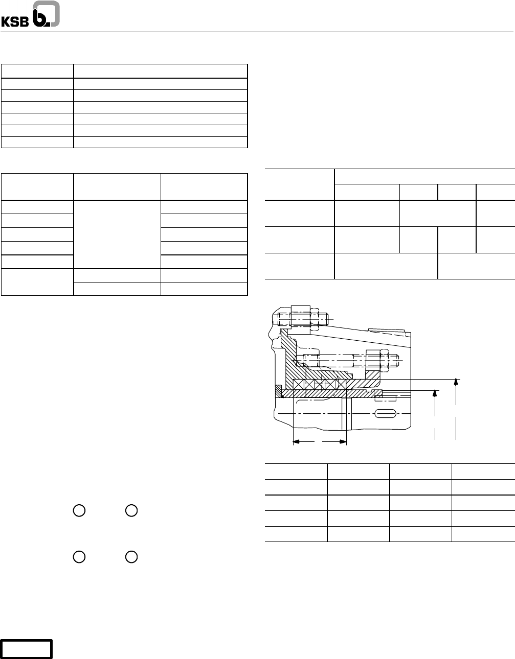
Fig. 37
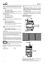
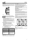
7.4.3 Seals
Gland packing
Before re-packing, thoroughly clean the packing chamber and
the gland cover.
Packing rings must be inserted so that the cut
edge of each ring is displaced by approx. 90° to
120° in relation to the previous one.
Slip the pre-stressed packing rings onto the shaft protecting
sleeve, press home the first packing ring with the help of the
gland cover. Each packing ring must be pressed into the
packing chamber individually, using the gland cover.
On gland packings with lantern ring (forvacuum operation), the
lantern ring is mounted instead of the next to last packing ring
(the lastpacking ring is locatedin the sealchamberon thepump
side).
Tighten the gland cover by hand at first. Use a feeler gauge to
check the level position of the gland cover. It must be easy to
turn the rotor by hand.
Leakage is normal duringpump commissioning.Afterapprox.5
minutes’ operating period, the amount of leakage can be
reducedby steadily tighteningthe nuts of the gland coverby 1/6
of a turn. Keep an eye on the amount of leakage and the water
temperature. It takes several hours of pump operation for the
gland to be adjusted completely. There must be a high leakage
rate during the running-in period.
Repeat this procedure every 5 minutesuntila minimum valueis
reached.
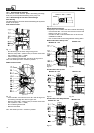
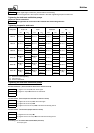
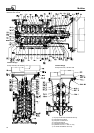
Dimensions in
Pump size
D
i
m
e
n
s
i
o
n
s
i
n
mm
32 - 50 - 65
100 125 150
Packing
cross-section
10 j 12,5 j 16 j
Length of
packing cord
≈181 ≈223 ≈254 ≈306
Number of
packing rings
5 6
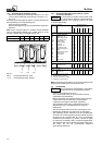
Stuffing box housing
Pump size
d
i
d
a
l
32 - 50 - 65 45 65 50
100 56 80 60
125 66 90 72
150 78 110 96
Fig. 38 Gland chamber dimensions