


Caution
Caution
Multitec
12
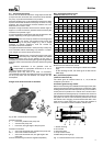
6.1.3 Contact guard
In compliance with health and safety regulations the
pump must not be operated without a coupling guard. If
the customer specifically requests not to include a coupling
guard in our delivery, then the operator must supply one.
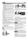
6.1.4 Connection to power supply
Ifthe pump is equipped with an electric motor,connection to the
power supply must be effected by a trained electrician only.
Check available mains voltage against the data on the motor
rating plate and select appropriate start-up method.
Make sure thatin the case ofthree-phase motors with star-delta
starting method switching over from starto delta will beeffected
at very short intervals. Prolonged switch-over intervals will
result in pump damage.
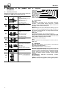
Time relay setting for star-delta starting
Motor rating Ytimetobeset
≦ 30 kW
>30kW
3sec. ± 30 %
5sec. ± 30 %
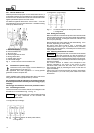
6.1.5 Start-up
Start-up procedure
- The discharge-side shut-off valve must be closed.
- Start-up must proceed without abnormal vibrations or
noises.
- An automatic check valve installed must open steadily when
the operating speed has been reached, without abnormal
noise, vibrations or increased power consumption of the
unit.
- Open the discharge-side shut-off valve.
- After the duty point has been reached, check motor input
power and bearing temperature.
After the operating temperature has been reached, switch off
the pump and re-tighten the bolts at the connecting flanges.
In the event of abnormal noise, vibrations,
temperatures or leakage, switch off the unit
immediately and re-start it only after the cause for the problem
has been eliminated.
Increased temperatures at the rolling element bearings after
commissioning are caused by the running-in process. The final
bearing temperature will be reached only after a certain
operating period (up to 48 h, depending on operating
conditions).
6.1.6 Shutdown
Close the shut-off valve in the discharge line.
If the discharge line is equipped with a non-return or check
valve, the shut-off elementmay remain open ifthere is sufficient
backpressure.
- Switch off the motor, making sure that the unit runs down
smoothly to a standstill.
- For prolonged shutdown, close the shut-off valve in the
suction line. Also close the auxiliary feed lines.
- The shaft seal in pumps where the liquid is fed in under
vacuum must also be supplied with barrier liquid during
standstill.
- In the event of frost and/or prolonged shutdowns, the pump
must be drained or otherwise protected against freezing.
Ifthe pump has to remain operationalduring shutdown periods,
it must be started up regularly for at least 5 minutes (see also
6.3):
- fire-fighting pumps at least once a month
- drinking water pumps at least once in 48 hours
- stand-by pumps at least once a week
(It is better to operate the pumps by alternating daily.)
During these periodic check runs also check the integrity and
proper functioning of the auxiliary feed lines.
6.1.7 Final check
After the pump has been primed, it must be easy to rotate the
coupling/ shaft by hand.
There must be no impermissible leakage at the s haft seal
during pump operation.
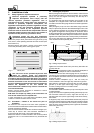
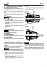
Gland packing
The gland packing has been fitted in the factory. Its permanent
compression can only be set after several hours of pump
operation. During this running-in period, gland leakage will be
higher than during normal pump operation. Check the
temperature of the leakage.
Final adjustment of the gland packing is made gradually after
havingallowedfora sufficientrunning-inperiod,so thatleakage
is reduced to individual drops (approx. 20 drops per minute).
Tightening the glandcover too early ortoo hard withoutallowing
for a sufficient running-in period would cause a local
temperature rise and insufficient lubrication, resulting in the
destruction of the gland packing, premature wear on the shaft
protecting sleeve and higher, uncontrollable leakage.
For speed controlled pumps or fluctuating inlet pressure, no
gland packing should be used, if possible. Changing pressures
make it difficult to set an even and controlled leakage rate.
Should such conditions occur, leakage of the
gland packing must not be prevented under any
operating conditions. At increased inlet pressure and/or
increased speed, the inevitably higher leakage of the gland
packing must not be reduced by re-tightening the gland bolts.
The minimumleakagerate mustonly be set atthe lowestspeed
and/or lowest inlet pressure.
Mechanical seal
The mechanicalseal assembly has beenadjustedandinstalled
in the factory. Itis maintenance-free.Check the sealforleakage
occasionally.
During commissioning, increased leakage may occur for a
short period of time. If leakage remains high, immediately
switch off the pump and investigate the leakage cause, e.g.
contaminated fluid handled or previous dry running due to
inadequate v enting of the pump unit.
Cooled mechanical seal (seal code 64)
If the pump is fitted with a cooled mechanical seal (seal code
64), vent the seal chamber as described in 6.1.1.
6.2 Operating limits
The hydraulic system is designed for pure or slightly
contaminated liquids (max. solids content: 20 ppm). Make sure
that the operating limits indicated in the order confirmation are
complied with.
6.2.1 Temperature of the fluid pumped
The pump must not be operated at temperatures exceeding
thosespecified on the nameplateor in the technicaldata sheet.