8
Installation Instructions and Owner’s Manual
Unvented LP-Gas Fired Buddy Wall-Mount Heater
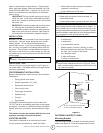
cleaning. A sediment trap traps moisture and con-
taminants. This keeps them from going into heater. If
sediment trap is not installed or is installed improperly,
heater may not run correctly.
IMPORTANT: Hold pressure regulator with wrench
when connecting it to gas piping and/or ttings.
CHECKING GAS CONNECTIONS
WARNING: Test all gas piping and connections for
leaks after installing or servicing. Correct all leaks
at once.
WARNING: Never use an open ame to check for
a gas leak. Apply a mixture of liquid soap and water
to all joints. Bubbles forming show a leak. Correct
all leaks at once.
PRESSURE TESTING GAS SUPPLY PIPING
SYSTEM
Test pressure in Excess of ½ psig (3.5kPa)
1. Disconnect appliance with its appliance main
gas valve (control valve) and equipment shutoff
valve from gas supply piping system. Pres-
sures in excess of ½ psig will damage heater
regulator.
2. Cap off open end of gas pipe where equipment
shutoff valve was connected.
3. Pressurize supply piping system by either using
compressed air or opening main gas valve on
or near gas meter.
4. Check all connections and joints in gas supply
piping system. Apply mixture of liquid soap and
water to gas joints. Bubbles forming show a
leak.
5. Correct all leaks at once.
6. Depressurize and relieve pressure in supply
piping system.
7. Reconnect heater and equipment shutoff valve
to gas supply.
8. Reconnected ttings must be checked for leaks
in next section.
Test Pressure Equal To or Less Than ½ psig
(3.5 kPa)
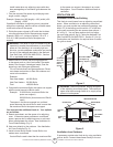
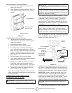
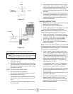
1. Close equipment shutoff valve (see gure 13).
2. Pressurize supply piping system by either using
compressed air or opening propane/LP supply
valve.
3. Check all joints from the propane/LP supply
valve to equipment shutoff valve (see gure
14). Apply mixture of liquid soap and water to
gas joints. Bubbles forming show a leak.
4. Correct all leaks at once.
5. Depressurize and relieve pressure from supply
piping system.
LIGHTING / OPerATING INSTrucTIONS FOr
uSe wITH HOSe cONNecTed TO A reMOTe
cYLINder, MAXIMuM SIZe 20 LBS:
• This Heater may be used in a Recreational Enclosure or
Temporary Construction Work Enclosure with a Remote
Refillable Propane Cylinder ONLY when the Cylinder
is Located Outdoors and the Heater is Used with Mr.
Heater Hose assembly supplied.
• dANGer: NEVER bring a refillable propane cylinder
indoors. A fire or explosion can occur causing property
damage, serious injury or death!
• Inspect the hose before each use of the heater. If there
is excessive abrasion or wear, or the hose is cut, replace
prior to using the heater with one of the Mr. Heater
Hose assembly supplied (see parts list).
• The propane cylinder must include a listed overfilling
protection device as well as a collar to protect the cylin-
der valve.
• Heater must be in an upright position during operation.
• Make sure five-position Control Knob is in “OFF” posi-
tion.
• Screw hose connector into regulator on heater and
screw connector on other end of hose into a regulated
LP-gas supply cylinder valve. Tighten all hose connec-
tions.
• Open valve at LP-gas supply cylinder.
• Check all hose connections for leaks with soapy water
at the threaded connection on heater where the hose
connector screws into the regulator and at LP-gas supply
cylinder.
Pressure Testing Heater Gas Connections:
1. Make sure that the heater supply piping sys-
tem is connected and has been leak tested as
described above.
2. Make sure control knob of heater is in OFF
position.
3. Open equipment shutoff valve (see gure 13).
4. Open propane/LP supply valve.
5. Check all joints from equipment shutoff valve
to control valve (see gure 14). Apply mixture
of liquid soap and water to gas joints. Bubbles
forming show a leak.
6. Correct all leaks at once.
7. Light heater (see Operating Your Heater, pages
11 and 12 for thermostat models or pages 9
and 10 for non-thermostat models). Check the
rest of the internal joints for leaks.
8. Turn off heater (see To Turn OFF Gas to Appli-
ance, page 12 for thermostat models and page
11 for non-thermostat models).
9. Replace lower front panel.


