


6
Mr. Heater, Inc. | Kerosene Forced Air Heater Operating Instructions and Owner’s Manual
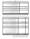
Model MH125KTR, MH175KTR and MH210KTR heaters are equipped with a diagnostic control board and flashing LED error indicator. This
flashing LED signals indicate unit operation status. See the following diagnostic guide for unit status and corrective action if necessary.
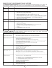
DIAGNOSTIC SAFETY SHUTDOWN AND TROUBLE SHOOTING
LED UNIT OPERATION TROUBLE SHOOTING
Steady ON System Check System performing self test. No action required.
Steady OFF Operation OK No action required.
2 Flashes No flame detected Heater fails to start during the first 30 sec. of operation.
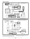
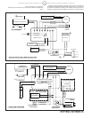
Check wiring to motor (per wiring schematic in manual).1.
Make sure that the pressure gauge is in place and not damaged.2.
Adjust pressure for proper heater operation per manual.3.
With heater disconnected from AC source, rotate fan clockwise to verify motor is free.4.
Remove air filter housing from motor and inspect the pump rotor for damage. If damaged, replace rotor assembly.5.
If wiring is correct, pump rotor is okay, and motor is not rotating freely, replace motor or power-pack assembly.6.
If problem persists, replace oil flame control assembly.7.
Check for spark arching from the electrode assembly (ref. 50), to the combustion cylinder (ref. 39).8.
Check the cad cell (ref. 38) for 9. continuity.
3 Flashes High limit switch
failure
Make sure heater is cooled off, press reset switch and retry.1.
4 Flashes CAD Cell Failure Check wiring to cad cell (per wiring schematic in manual).1.
Clean cad cell photo cell.2.
Slide cad cell out of cad cell holder.•
Push the photo cell out of the black rubber cad cell housing by pushing on the 2 purple wires.•
Clean the photo cell with a soft cloth and rubbing alcohol.•
Pull the photo cell back into the cad cell housing and reinstall into holder.•
Test heater.•
If the heater still does not operate, replace cad cell.3.
Replace oil flame control assembly.4.
Power Light Power to control Sensing power. No action required.1.
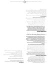
Model MH50KR and MH75KTR heaters are NOT equipped with a diagnostic control board or flashing LED error indicator. See the following
troubleshooting guide for unit status and corrective action if necessary.
SYMPTOM TROUBLE SHOOTING
High limit switch Open Circuit 1) Make sure heater is cooled off, toggle switch to “OFF” position, wait 5 minutes and retry.
Sparks, calling for flame, but 1) Check wiring to motor (per wiring schematic in manual).
no or slow motor operation 2) Make sure that the pressure gauge is in place and not damaged.
3) Adjust pressure for proper heater operation per manual.
4) With heater disconnected from AC source, rotate fan clockwise to verify motor is free.
5) Remove air filter housing from motor and inspect the pump rotor for damage. If damaged, replace rotor assembly.
6) If wiring is correct, pump rotor is okay, and motor is not rotating freely, replace motor or power-pack assembly.
7) If problem persists, replace oil flame control assembly.
8) Check for spark arching from the electrode assembly, to the combustion cylinder.
9) Check the cad cell for continuity.
No Spark 1) Check length and gage of extension cord for proper amp. draw. (Check requirements on page 4.)
2) Check wiring to igniter (per wiring schematic in manual).
3) Check gap between electrode probes (2.3 - 3 mm).
4) Still no spark, replace igniter assembly.
5) Replace oil flame control assembly.
Abnormal Motor Operation - 1) Motor speed too low (Motor should operate at 3450rpm) - Replace motor.
Motor overheats or Stops 2) With heater disconnected from AC source, rotate fan clockwise to verify motor is free.
3) Remove air filter housing from motor and inspect the pump rotor for damage. If damaged, replace rotor
assembly.
4) If wiring is correct, pump rotor is okay, and motor is not rotating freely, replace motor or power-pack assembly.
5) Replace oil flame control assembly.
Unable to Detect Flame 1) Check wiring to cad cell (per wiring schematic in manual).
2) Clean cad cell photo cell.
a) Slide cad cell out of cad cell holder.
b) Push the photo cell out of the black rubber cad cell housing by pushing on the 2 purple wires.
c) Clean the photo cell with a soft cloth and rubbing alcohol.
d) Pull the photo cell back into the cad cell housing and reinstall into holder.
e) Test heater.
3) If the heater still does not operate, replace cad cell.
4) Replace oil flame control assembly.
Flame Control Failure 1) Check wiring in heater (per wiring schematic in manual).
2) Replace oil flame control assembly.