


Lift Canop
y to ceiling aligning the k
ey hole slots
with the screws on the bottom of the Mounting
bracket. Rotate the canopy Counter Clockwise
to lock in place. Tighten the screws to secure
the Canop
y
. See inset for K
eyhole shape
29
A
ttach blades to blade arms with
screws and w
ashers supplied. Repeat
for all 5 blades.
30
Re-install safety bar removed in step
3 by placing safety bar on screws,
sliding into place, and tightening the
2 screws.
23
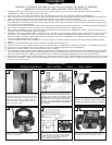
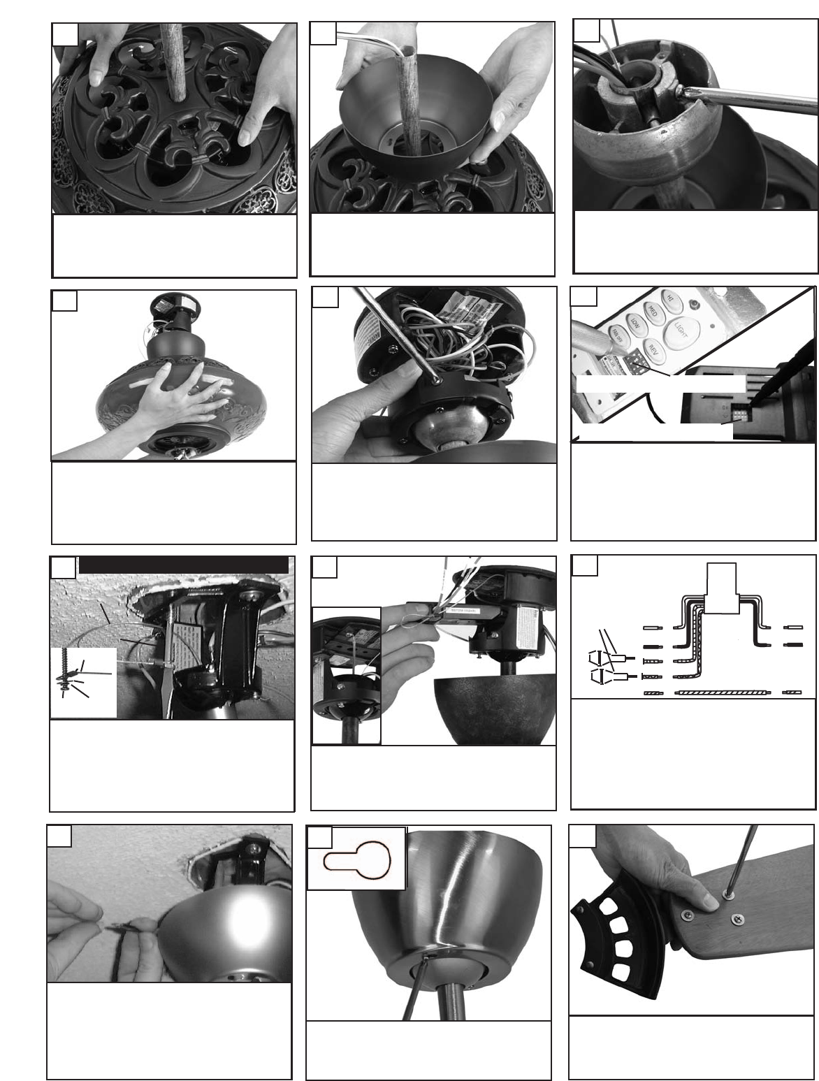
Mak
e wire connections to power source using
wire nuts pro
vided. Make sure that no filiments
are outside of the wire nut. After making the
wire connections, the wires should be spread
apart with the grounded conductor and the
equipment-grounding conductor on one side of
the outlet bo
x and ungrounded conductor on
the other side of the outlet box.
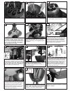
28
Set dip switches on the Remote Transmitter and Remote
Receiver to the same settings. This must be done so the
units will communcate properly.
If you have other fans you
can set to control from one transmitter by setting both
receivers the same as the transmitter. If you have more
than one fan with remote. You can set the dip switches to
different positiosns to have seperate control.
R
emote Transmitter Dip swtiches
Re
mote Receiver Dip switches
24
Place canopy over downrod.
20
Place upper housing over downrod.
19
Install ball on downrod, replace cross
pin and tighen screw securely.
2
1
Hang assembled fan from the mounting brack-
et installed to ceiling in previous step. Make
sure the fan is hanging straight. Rotate fan
until the tab on the Mounting bracket engages
the slot on the Downrod Ball. This must be
done to prevent the fan body from rotating
when the blades are in motion.
22
Fan and light kit combinations over 70 lbs,
in both flush and downrod mode the safety
cable must be installed into the house struc-
ture beams using the 3” lag screws,washers,
and lock w
ashers. pro
vided. Make sure that
when the safety cable is fully extended the
lead wires are longer than the cable and no
stress is placed on the lead wires.
25
Safety cable installation
Safety Cable
Lag Screw
safety
cable
3” lag
screw
lock
washer
washer
Install remote receiv
er b
y sliding into
opening in the Mounting bracket. Make
sure that the dip switches on the
Transmitter and the Receiver are set to
the same position.
26
white
black
Make wiring connections as indicated above.
White from fan to white from remote marked
N. Or
ange from fan to Or
ange from remote
mark
ed Light/up
. Blue from fan to blue from
remote marked down light. Black from fan to
Black from remote marked L. White from
house to white from remote marked AC N .
Black from house to Black from remote
mark
ed AC L. Connect all green ground wires
to Ground wire from House.
orange
blue
Green
white
black
House
Fan
27
fuses