


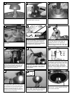

Raise fan with downrod assembled to
the ceiling bracket and hang fan
assembly. Be sure to rotate the
downrod ball so that the notch in the
bracket engages the slot in the ball.
Tighten 2 downrod set screws and
lock nuts.
10
12
Install keeper into cross pin.
9
I
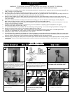
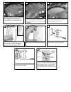
nstall downrod into yoke.
7
Align hole in downrod with hole in
yoke and install cross pin.
8
Loosen 2 screws with key slots and
remo
v
e the 1 screw without k
et slot.
Sa
v
e screw remo
v
ed.
18
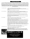
Set dip switches on the Re
mote Tra
nsmitter and Remote
Receiver to the same settings. This must be done so the
units will communcate properly. If you have other fans you
can set to control from one transmitter by setting both
receivers the same as the transmitter. If you have more
than one fan with remote. You can set the dip switches to
different positiosns to have seperate control.
R
emote Transmitter Dip swtiches
R
emote Receiver Dip switches
11
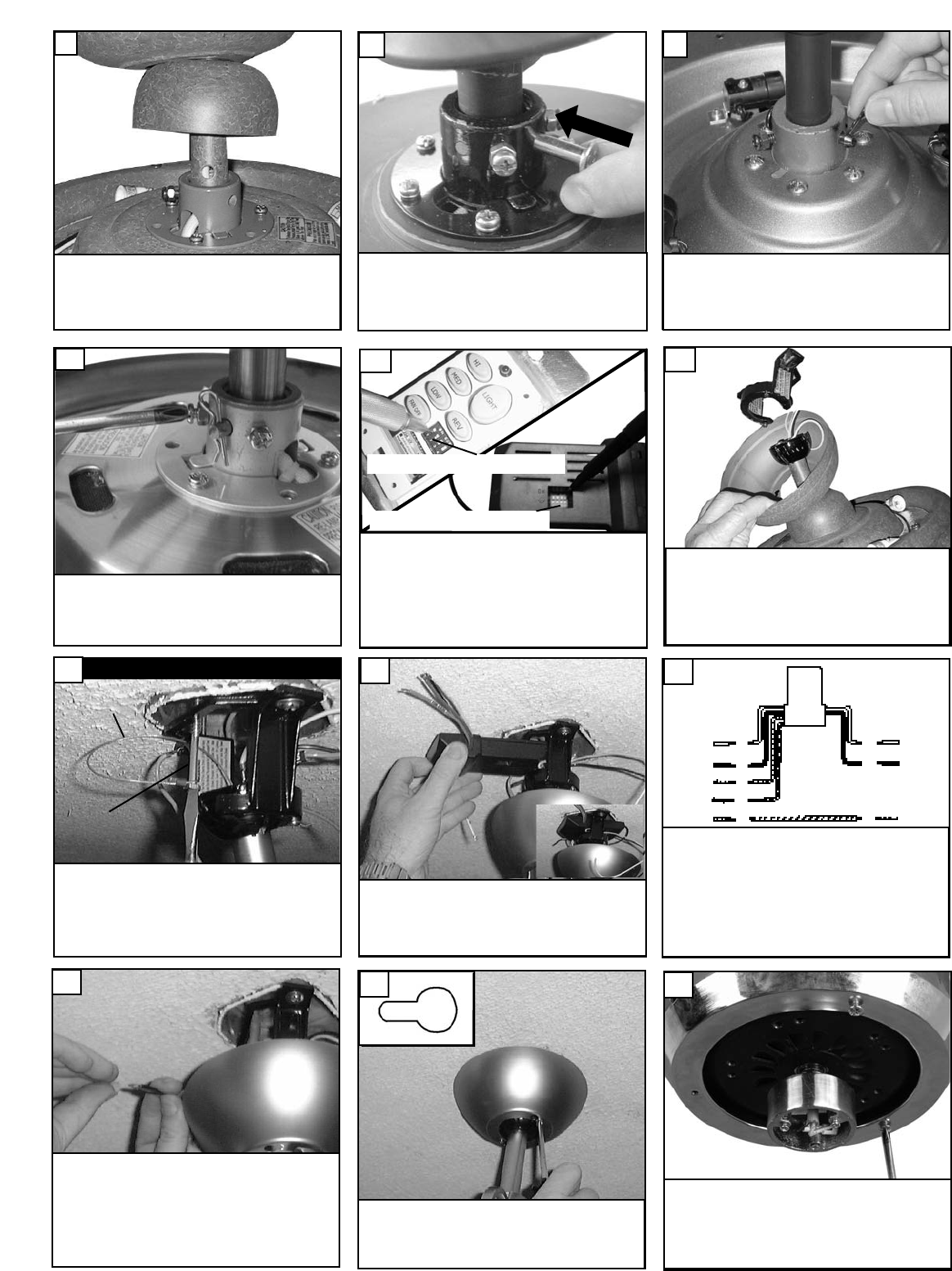
For Canadian installation in both flush and
downrod mode the safety cable must be
installed into the house structure beams using
the 3” lag screws provided. Make sure that
when the safety cable is fully extended the
leadwires are longer than the cable and no
stress is placed on the leadwires.
13
Canadian mounting only
Safety Cable
Lag Screw
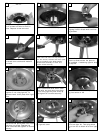
Make wire connections to power source using
wire nuts provided. Mak
e sure that no filiments
are outside of the wirenut. After making the
wire connections, the wires should be spread
apart with the grounded conductor and the
equipment-grounding conductor on one side of
the outlet box and ungrounded conductor on
the other side of the outlet box.
16
Lift Canop
y to ceiling aligning the k
ey hole slots
with the screws on the bottom of the Mounting
bracket. Rotate the canopy Counter Clockwise
to lock in place. Tighten the screws to secure
the Canop
y
. See inset for K
eyhole shape
17
white
Red
Mak
e wiring connections as indicated abo
v
e.
White from fan to white from remote marked
N. Or
ange from fan to Or
ange from remote
marked Light/up. Blue from fan to blue from
remote marked down light. Black from fan to
Red from remote marked L. White from
house to white from remote marked AC N .
Black from house to Black from remote
marked AC L. Connect all green ground wires
to Ground wire from House.
Install remote receiver by sliding into opening in
the Mounting bracket. Make sure that the dip
switches on the T
ransmitter and the Receiver
are set to the same position. See Fig 37 for
remote oper
ation
orange
blue
Green
white
black
House
Fan
14
15