


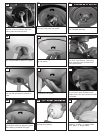
Install two screws corresponding with the
“L” shaped holes in the canopy only part
way so that canopy can twist into place.
Remove the all thread studs from the
lower part of the mounting bracket.
Lift fan to mounting bracket, aligning the “L”
shape holes with the scresws on the mount-
ing bracket. Turn the fan clockwise to lock
in position. Install the other two screws and
tighten securely.
33
39
Hang fan from mounting bracket by
the hands free hook into a closed
hole on the edge of the Canopy.
Note: For Canadian mounting refer to
Step #10.
Place canopy on top of the fan motor allowing the
yoke, wires and safety cable to pass through the
large hole in the center of the canopy. Align the 3
larger holes around the center hole with the 3
screws still installed in the fan. Install 3 screws
removed into small holes in canopy to make it a
f
lush mount canopy and tighten screws securely.
32
34
Canopy
Center
Hole
Larger
holes
Smaller
holes
Hands free hook
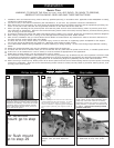
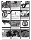
Remove 2 screws in yoke and keeper
then cross pin (see insert). Remove 3
screws with keyhole slots from top of
fan.
31
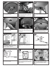
Slide remote receiver into mounting
br
ack
et.
37
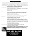
Make wiring connections as indicated above.
White from fan to white from remote marked
N. Blue from fan to blue from remote marked
light. Black from fan to Black from remote
marked L. White from house to white from
remote marked AC N . Black from house to
Black from remote marked AC L. Connect all
green ground wires to Ground wire from
House.
35
white
black
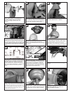
Set dip switches on the Remote Transmitter and Remote
Re
ceiver to the same settings. This must be done so the
units will communcate properly. If you have other fans you
can set to control from one transmitter by setting both
receivers the same as the transmitter. If you have more
than one fan with remote. You can set the dip switches to
different positiosns to have seperate control.
Remote Transmitter Dip swtiches
R
emote Receiver Dip switches
36
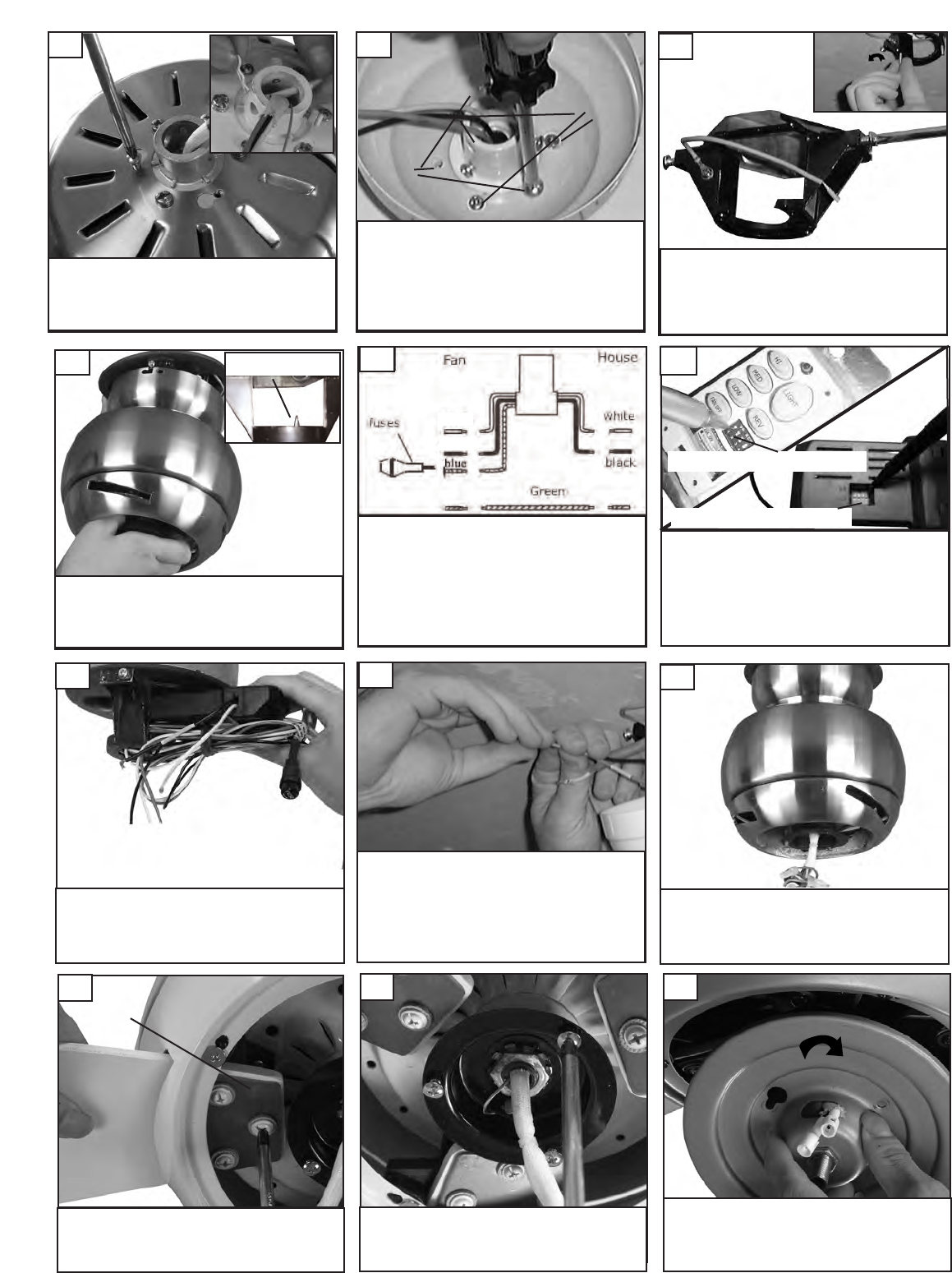
Make wire connections to power source using wire nuts
provided. Make sure that no filiments are outside of
the wirenut. After making the wire connections, the
wires should be spread apart with the grounded con-
ductor and the equipment-grounding conductor on one
side of the outlet box and ungrounded conductor on
the other side of the outlet box.
38
Align the blade and then the blade
plate with castings on motor to
attach blades to motor.
40
Blade plate
Loosen 2 screws with key slots and
remove 1 screw without slot from
motor plate and save screw.
41
Install light plate by twisting plate
with key hole slots into place. .
42