


27D8520 11
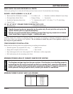
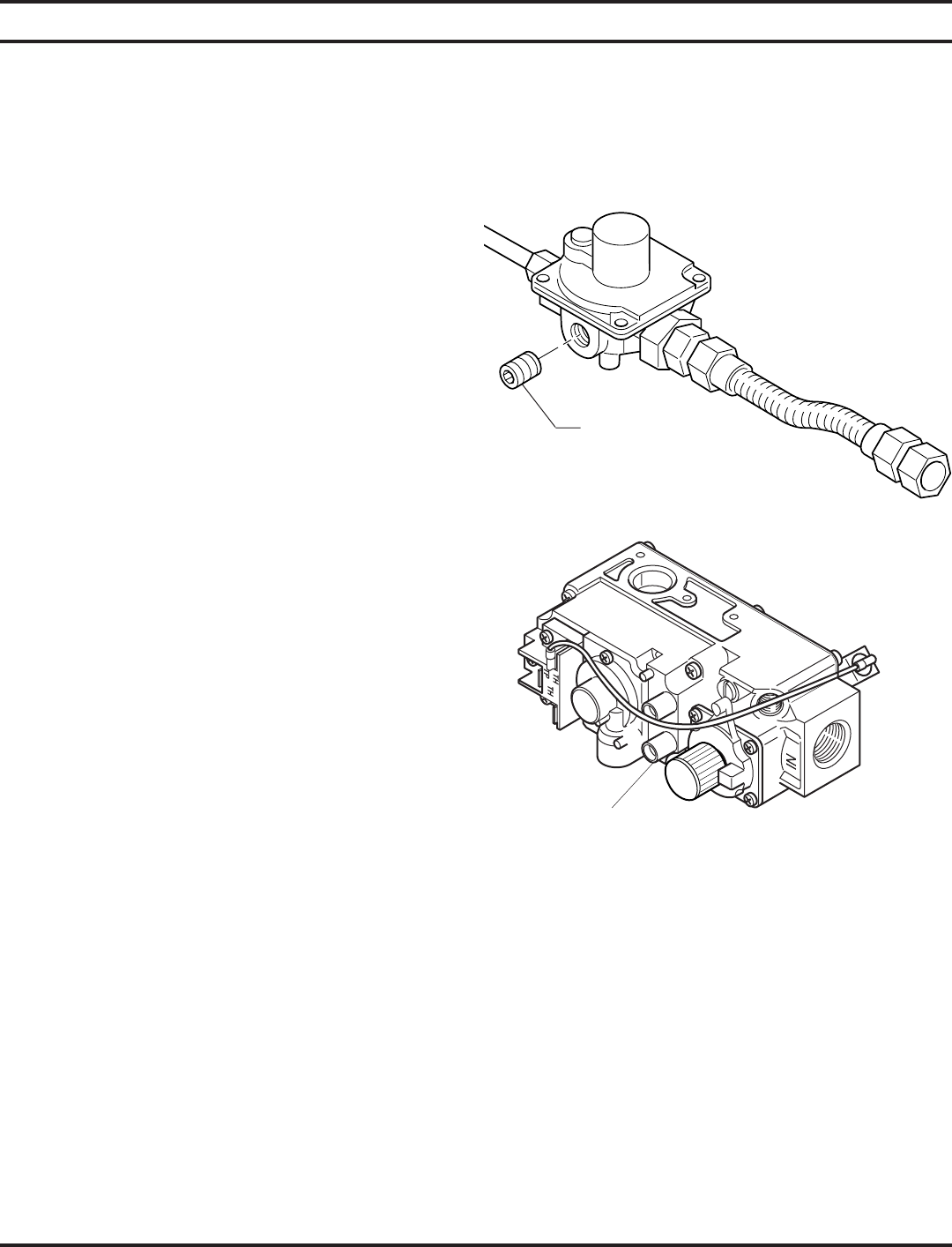
Figure 9 - Pressure Test Point Location
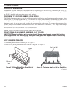
Test Plug
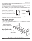
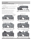
MANUAL CONTROL (Figure 9)
The pressure regulator is preset and locked to discourage
tampering. If the pressure is not as specified, replace with
the correct part from the parts list in this manual.
Remove 1/8" NPT plug, located on side of regulator body.
Install fitting and tubing to pressure gauge. After taking
pressure reading, re-install test plug. which should be
checked at the pressure test point. Check for gas leaks.
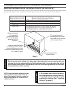
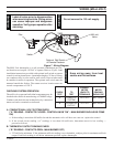
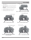
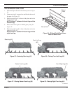
Test Port
“Out”
Figure 10 - Pressure Test Point Location
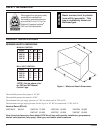
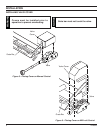
CONNECTING THE GAS
The gas log set gas inlet connection is 3/8" NPT at the regulator, inlet on the right side facing the gas log. If a left side con-
nection is required, the connecting pipe may be led under the rear of the gas logs or behind the grate for connection to the
inlet.
Test all gas joints from the gas meter to the appliance regulator for leaks using a gas analyzer or soap and water solution
after completing connection. DO NOT USE AN OPEN FLAME.
Check the gas pressure with the appliance burning.
MILLI-VOLT CONTROL (Figure 10)
The valve regulator controls the burner pressure which should
be checked at the pressure test point. Turn captured screw
counter clockwise 2 or 3 turns and then place tubing to pres-
sure gauge over test point (Use test port labeled “OUT”).
After taking pressure reading, be sure and turn captured
screw clockwise firmly to re-seal. Do not over torque. Check
for gas leaks.