46D0232
12
SS38 Direct Vent Gas Stove
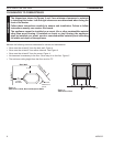
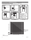
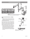
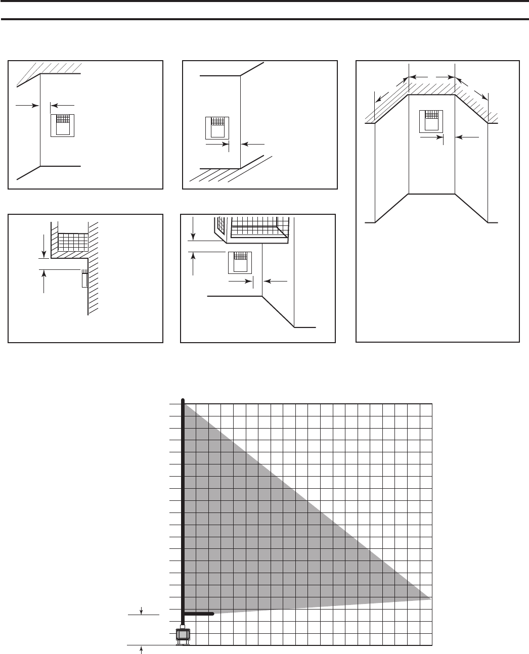
Any vent
configuration within
the shaded areas is
acceptable.
Figure 7 -
Allowable Venting Chart
V
G G=6" (152mm)
F
F=6" (152mm)
V
V
G
G = Combustible 24"(610mm)
Noncombustible 18"(457mm)
Combustible &
Noncombustible
H = 24" (610mm)
J = 20" (508mm)
V
H
J
C = Maximum depth of 48" (1219mm)
for alcove location
D = Minimum width for back wall of
alcove location
Combustible - 38" (965mm)
Noncombustible - 24" (610mm)
E = Clearance from corner in alcove
location
Combustible - 6" (152mm)
Noncombustible - 2" (51mm)
E
V
D
C
C
Inside Corner
Alcove Location
Outside Corner
Balcony with No Side Wall Balcony with Perpendicular
Side Wall
FP1951
termination clearances
FP1951
2
4
6
8
10
12
14
16
18
20
22
24
26
28
30
32
34
36
38
40
1 2 3 4 5 6 7 8 9 10 11 12 13 14 15 16 17 18 19 20
47.5"
(121cm)
ST1102
VS38 vent graph
ST1102


