


51D0528
17
LX Series Direct Vent Gas Fireplace
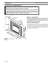
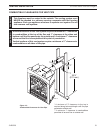
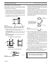
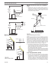
When installed as a rear vent unit this appliance may be
vented directly to a termination located on the rear outside
termination behind the appliance
• 45° elbows may only be attached to rear when used to
direct the flue skyward (to achieve additional rise). Do
not attach 45° elbows to rear of appliance in which the
flue turns either left or right and terminates horizontal.
• The maximum horizontal distance between the rear
of the appliance and the outside face of the outside
termination is 20" (508 m). Figure 15
DVR584-600
Rear vent no elbows
2/99 djt
Figure 14 -
Rear Vent Application,
Maximum Horizontal Distance
20"(508 mm)
Maximum
DVR584
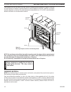
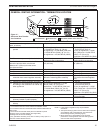
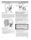
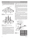
1. Locate and cut the vent opening in the wall. For com-
bustible walls first frame in opening. Figure 15
Cut a 11Z\x"H x 9Z\x" W (292 x 24
mm) hole through the exterior wall and frame as shown.
Figure 15
Hole opening should be 7Z\x"
(190 mm) in diameter.
VO584-100
Vent Opening
2/99 djt
9Z\x"
(241 mm)
11Z\x"
(292 mm)
Fireplace Hearth
Framing Detail
7Z\x"
(190 mm)
Fireplace Hearth
VO584-100
Figure 15 -
Locate Vent Opening on Wall
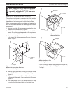
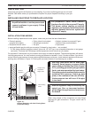
FP1953
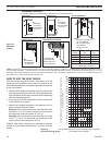
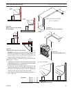
rigid pipe
Figure 16 -
Rigid Vent Pipe Connections
Female
Locking Lugs
Male Slots
FP1953
2. Rigid vent pipes and fittings have special twist-lock
connections. Assemble the desired combination of pipe
and elbows to the appliance adaptor with pipe seams
oriented towards the wall or floor.
Twist-lock Procedure: The female ends of the pipes
and fittings have three locking lugs (indentations).
These lugs will slide straight into matching slots on
the male end of adjacent pipes and fittings. Push the
pipe sections together and twist one section clockwise
approximately one-quarter turn until the sections are
fully locked. Figure 16
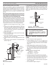
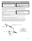
3. Attach vent pipe assembly to the fireplace. Set fireplace
in front of its permanent location to insure minimum
clearances. Mark the wall for a 11Z\x"H x 9Z\x"W (292 x 24
mm) rectangle hole (for noncombustible material such
as masonry block or concrete, a 7Z\x" [190 mm] diameter
hole is acceptable). Figure 15. The center of the hole
should line up with the center line of the horizontal rigid
vent pipe end. Be sure to allow for minimum rise. Cut
a 11Z\x" x 9Z\x" (292 X 241 mm) rectangle hole through
combustible exterior wall (7Z\x" [190 mm] diameter hole
if noncombustible). Frame as necessary. Allow 1/4"
minimum rise per foot. Figure 15
4. Apply a bead of non-hardening mastic around the
outside edge of vent cap. Position the vent cap in the
center of hole on the exterior wall with the word “UP”
on the vent cap facing up. Insure proper clearance of
1" to combustibles is maintained. Attach the vent cap
with four wood screws supplied. Figure 17
Replace the wood screws with appropriate fasteners
for stucco, brick, concrete, or other types of siding.