


16
51D0528
LX Series Direct Vent Gas Fireplace
40
38
36
34
32
30
28
26
24
22
20
18
16
14
12
10
8
6
4
2
2 4 6 8 10 12 14 16 18 20
eg: A
FP2714
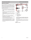
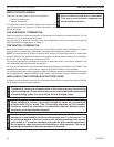
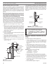
sidewall vent graph
The Vent Graph should be read in conjunction with the
following vent installation instructions to determine the
relationship between the vertical and horizontal dimensions
of the vent system.
1. Determine the height of the center of the horizontal vent
pipe exiting through the outer wall. Using this dimension
on the Sidewall Vent Graph, locate the point intersecting
with the slanted graph line.
2. From the point of this intersection, draw a vertical line
to the bottom of the graph.
3. Select the indicated dimension, and position the fire-
place in accordance with same.
If the vertical dimension from the floor of the
fireplace is 11' (3.4 m) the horizontal run to the face of
the outer wall must not exceed 14' (4.3 m).
If the vertical dimension from the floor of the
unit is 7’ (2.14 m), the horizontal run to the face of the
outer wall must not exceed 8Z\x' (2.6 m).
Sidewall Vent Graph showing the relationship between
vertical and horizontal dimensions for a Direct Vent flue
system.
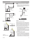
Figure 13 -
Rear Wall Venting Graph
Horizontal Dimension From the Outside Face of the Wall
to the Back of the Fireplace
Vertical Dimension From the Floor of Unit to the Center of the
Horizontal Vent Pipe
Dimensions in
Feet
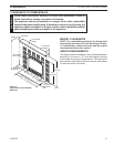
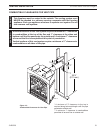
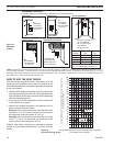
Outside Corner
Inside Corner
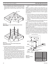
Termination Clearances
Termination clearances for buildings with combustible and noncombustible exteriors.
G =
Combustible
6" (152 mm)
Noncombustible
2" (51 mm)
F =
Combustible
6" (152 mm)
Noncombustible
2" (51 mm)
G
Balcony -
with no side wall
M =
Combustible &
Noncombustible
12" (305 mm)
M
Balcony -
with perpendicular side wall
M = 24" (610 mm)
P = 20” (508 mm)
M
F
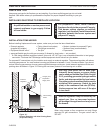
Alcove Applications*
C
D
C
E
V
V
Combustible &
Noncombustible
V
V
V
E = Min. 6” (152 mm) for
non-vinyl sidewalls
Min. 12” (305 mm) for
vinyl sidewalls
O = 8’ (2.4 m) Min.
O
P
Figure 12 -
Allowable
Venting
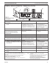
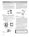
584-15
No.
of Caps DMin. CMax.
1 3’ (914 mm) 2 x DActual
2 6’ (1.8 m) 1 x DActual
3 9’ (2.7 m) 2/3 x DActual
4 12’ (3.7 m) 1/2 x DActual
DMin. = # of Termination caps x 3
CMax. = (2 / # termination caps) x DActual
Termination in an alcove space (spaces open only on one side and with an overhang) is permitted with the dimensions specified for vinyl or
non-vinyl siding and soffits. 1. There must be a 3’ (914 mm) minimum between termination caps. 2. All mechanical air intakes within 10’ (1 m) of a
termination cap must be a minimum of 3’ (914 mm) below the termination cap. 3. All gravity air intakes within 3’ (914 mm) of a termination cap must
be a minimum of 1’ (305 mm) below the termination cap.