


16
57D0016
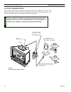
IDV380/IDV490 Fireplace Insert
Figure 15
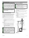
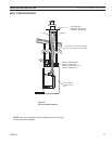
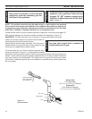
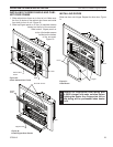
A listed manual shutoff is factory installed upstream of appliance. Union tee and plugged 1/8"
NPT pressure tapping point should be installed upstream of the appliance. Figure 15.
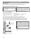
The main gas valve is for turning on or shutting off the gas to the insert.
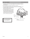
Check your building codes for any special requirements for
locating equipment shutoff valve to inserts.
Apply pipe joint sealant lightly to threads. This will prevent
excess sealant from going into pipe. Excess sealant in pipe
could result in clogged burner system valves.
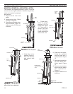
We recommend that you install a sediment trap/drip leg in
supply line as shown in Figure 15. Locate sediment trap/drip
leg where it is within reach for cleaning. Install in piping system between fuel supply and burner
system. Locate sediment trap/drip leg where trapped matter is not likely to freeze. A sediment
trap traps moisture and contaminants. This keeps them from going into the burner system
gas controls. If sediment trap/drip leg is not installed or is installed wrong, burner system may
not run properly.
NOTE : The gas line connection may be made using 1/2" rigid tubing or an approved
flex connector. Since some municipalities have additional local codes it is always best
to consult your local authorities and the current edition of the National Fuel Gas Code
ANSI.Z223.1, NFPA54. In Canada CSA-B149 (1 or 2) Installation Code.
3" Minimum
FP1931
gas connection
9/08
Approved Flexible
Gas Line Supplied
with Appliance
Tee Joint
Pipe Nipple
Cap
From Gas Meter
(4.5" w.c. to 10.5" w.c. Pressure)
From External Regulator
(11" w.c. to 13" w.c. Pressure)
Figure 15 -
Gas Connection