


HDV Series Direct Vent Gas Fireplace
6
56D3048
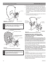
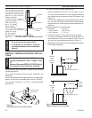
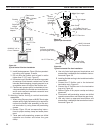
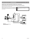
Termination
Cap
Storm Collar
Roof Sup-
port
Flashing
Rigid Pipe
Length
Flex to Pipe
Adapter
Firestop
UL1777 Flex
PIpe
DVFA/8
Adapter
Figure 38 -
Typical Vertical Flex Vent Installation
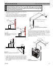
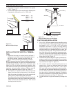
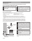
FP1975
pipe connection
Screws
(3 Places
equidistant
just above
gear clamp)
Rigid Pipe Length
Flex to Pipe Adapter
Gear Clamp
1C\v" Flexible Pipe and
Adapter Outer Collar Over-
lap
UL1777 Flex Vent
Figure 39 -
Typical Pipe Connection
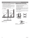
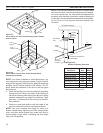
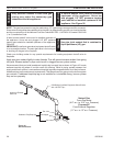
Gear Clamp
FP1976
horizontal flex
Screws
(3 Places equidistant
just above gear clamp)
Gear Clamp
UL1777 Flex Vent
1C\v" Flexible Pipe
and Collar Overlap
MHSC Horizontal
Vent Termination
Figure 40 -
Typical Horizontal Flex Vent Installation
1DA 5" x 8" to
4" x 6B\," Reducer
FP1974
. Install firestop spacers, Figure 38, when penetrat-
ing ceiling, attic spaces, or walls.
3. Do not allow the flexible vent to bend in radius
tighter than 5" (17 mm). Figure 37
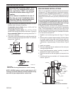
4. Horizontal runs of flexible vent shall be supported
at maximum foot intervals; vertical runs, five feet
intervals. Metal strapping, properly secured, is an
acceptable means to support the flexible vent.
5. Flexible vent spacers are to be installed at inter-
vals prescribed by the flexible vent manufacturer;
and in such a way as to maintain concentric inner
and outer vent spacing.
D. Attaching flexible venting to vertical termination
assemblies.
1. When using Simpson pipe, an MHSC flex-to-pipe
adapter and/or rigid pipe section(s) is required to
connect the flexible vent assembly to the verti-
cal termination by using three self-penetrating
screws.
. Review Figure 39 and corresponding instruc-
tions for proper overlap, clamp and screw place-
ment.
3. Three each self-penetrating screws are drilled
opposite one another and below the gear
clamp.
4. Use only listed and approved terminations and
accessories, installed per the installation instruc-
tions and Figure 38.
E. Installing flexible venting to horizontal termination
assemblies.
1. Connect the 5" flexible vent to the horizontal
termination as in Figure 40.
. Connect the 8" flexible vent to the termination
ring as in Figure 40.
3. Review Figure 40 for proper overlap and clamp
placement.
4. Three each self-penetrating screws are drilled
opposite one another and below the gear lamp.
5. Use only listed an approved terminations and
accessories, installed per the termination instruc-
tions and Figure 40.