


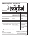
HBDV7 Series Direct Vent Gas Fireplace
16
54D8000
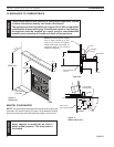
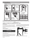
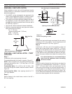
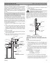
When installed as a rear vent unit this appliance may be
vented directly to a termination located on the rear wall
behind the appliance.
• Only MHSC venting components are approved to be
used in these applications (Refer to ‘Venting Compo-
nents’ listed for different installation requirements).
• The maximum horizontal distance between the rear of
the appliance (or end of the transition elbow in a cor-
ner application) and the outside face of the rear wall is
0” (508 mm). Figure 17
• Only one 45° elbow is allowed in these installations.
• Minimum clearances between vent pipe and combus-
tible materials are as follows:
Top - 3” (76 mm)
- except at outside wall 1" (5 mm)
Sides - 1” (5 mm)
Bottom - 1” (5 mm)
FP2292
rear vent top vu
20”
(508 mm)
Max.
Figure 17 -
Rear Vent Application, No Elbows
FP9
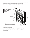
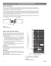
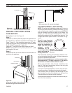
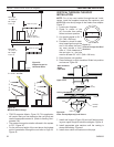
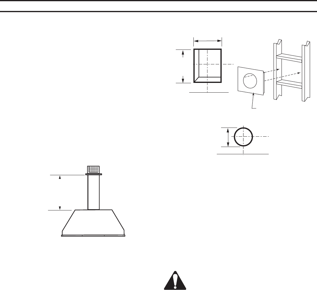
Locate and cut the vent opening in the wall.
For combustible walls first frame in opening. Figure 18
When using flex vent, the opening will have to be
measured according to the 1” (5 mm) rise in 4” (610
mm) vertical run.
Cut a 9B\,”H x 9B\,” W (44 x 44
mm) hole through the exterior wall and frame as shown.
Figure 18
Hole opening should be 7Z\x”
(191 mm) diameter.
Secure firestop to the inside frame, center in the 9B\," x
9B\," vent opening.
VO584-100
Vent Opening
2/99 djt
9B\,”
(44 mm)
Min.
Fireplace Hearth
Framing Detail
7Z\x”
(190 mm)
Fireplace Hearth
FP93
Figure 18 -
Locate vent opening on wall.
9B\,”
(44 mm) Min.
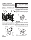
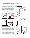
Measure the horizontal length requirement for the venting
including a ” (51 mm) overlap, i.e. from the elbow to the
outside wall face plus ” (51 mm). Figure 17
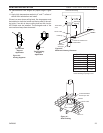
Install the 4” (10 mm) vent to the appliance collar and
secure with 3 sheet metal screws. Install the 7” (178 mm)
vent pipe to the appliance collar and secure with 3 sheet
metal screws. It is not necessary to seal this connection.
If a 45° elbow is being used attach the elbow to the appli-
ance in the same manner then attach the venting to the
elbow.
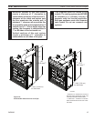
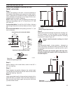
Guide the venting through the vent hole as you place the
appliance in its installed position. Guide the 4” (10 mm)
and 7” (178 mm) collar of the vent termination into the
outer ends of the venting. Do not force the termination. If
the vent pipes do not align with the termination, remove
and realign the venting at the appliance flue collars. Fig-
ure 19. Attach the termination to the wall as outlined in the
instruction sheet supplied with the termination.