


HBDV7 Series Direct Vent Gas Fireplace
14
54D8000
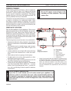
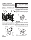
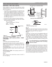
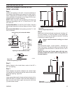
When using twist lock pipe it is not necessary to use sealant on the joints. The only areas of the
venting system that need to be sealed with high temperature silicone sealant are the sliding joints
of any telescopic vent section used in the system.
To join twist lock pipes together, simply align the beads of the male end with the grooves of the fe-
male end, twisting the pipe until the flange on the female end contacts external flange on the male
end. It is recommended that you secure the joints with three (3) sheet metal screws, however, this
is not mandatory with twist lock pipe. Figure 14
To make it easier to assembly the joints, we suggest putting a lubricant (Vaseline or similar) on the
male end of the twist lock pipe prior to assembly.
TWL100
Twist Lock Pipe
3/12/99 djt
Male End
Female End
Screw Holes
TWL100
Figure 14 -
Twist-lock Pipe Joints
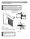
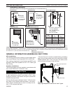
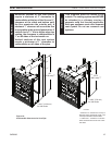
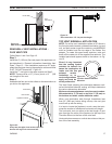
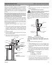
The Vent Graph should be read in conjunction with the
following vent installation instructions to determine the re-
lationship between the vertical and horizontal dimensions
of the vent system.
1. Determine the height of the center of the horizontal
vent pipe exiting through the outer wall. Using this di-
mension on the Sidewall Vent Graph, Figure 15, locate
the point intersecting with the slanted graph line.
. From the point of this intersection, draw a vertical line
to the bottom of the graph.
3. Select the indicated dimension, and position the fire-
place in accordance with same.
If the vertical dimension from the floor of the unit is 11’ (3.4
m) the horizontal run to the face of the outer wall must not
exceed 14’ (4.3 m).
If the vertical dimension from the floor of the unit is 7’ (.1
m), the horizontal run to the face of the outer wall must not
exceed 6’ (1.8 m).
Page 21
40
38
36
34
32
30
28
26
24
22
20
18
16
14
12
10
8
6
4
2
2 4 6 8 10 12 14 16 18 20
eg: A
FP2291
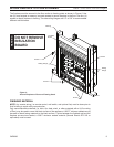
vent graph
X
Vertical Dimension from the Floor of Unit to the Center of
the Horizontal Vent Pipe
Horizontal Dimension From the Outside of Termination to
the Back of the Fireplace
Figure 15 -
Side Wall Venting Graph
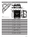
X = 9B\,” (753 mm) for 300 Models
X = 33Z\,” (841 mm) for 400 Models