


20 65D1009
LO
HI
OFF
SK
Y
TE
C
H
O
F
F
O
N
R
E
M
O
T
E
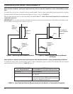
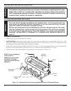
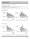
ELECTRICAL WIRING (MILLIVOLT)
A. COMPLETE MILLIVOLT SYSTEM CHECK
(“A” Reading - On/Off Switch contacts CLOSED - Control Knob “ON” - Main burner should come
ON)
a. If the reading is more than 175 millivolts and the automatic valve still does not come on, replace the control.
b. If the closed circuit reading (“A” reading) is less than 175 millivolts, determine cause for low reading, proceed to
Section B below.
B. Thermopile Output Reading Check
(“B” Reading - On/Off Switch contacts OPEN - Main burner OFF)
1. Check gas pressure to the unit. If gas pressure is within minimum and maximum on data plate, then check pilot
voltage, 500 millivolts minimum. If the minimum millivolt reading is not obtainable, replace pilot.
CHECKING SYSTEM OPERATION
The millivolt system and individual
components may be checked with
a millivolt meter having a 0-1000
mV range. Conduct each check
shown in chart below by connect-
ing meter test leads to terminals as
indicated.
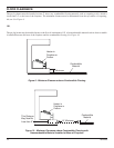
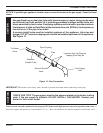
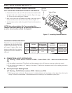
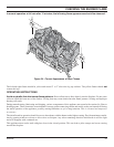
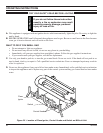
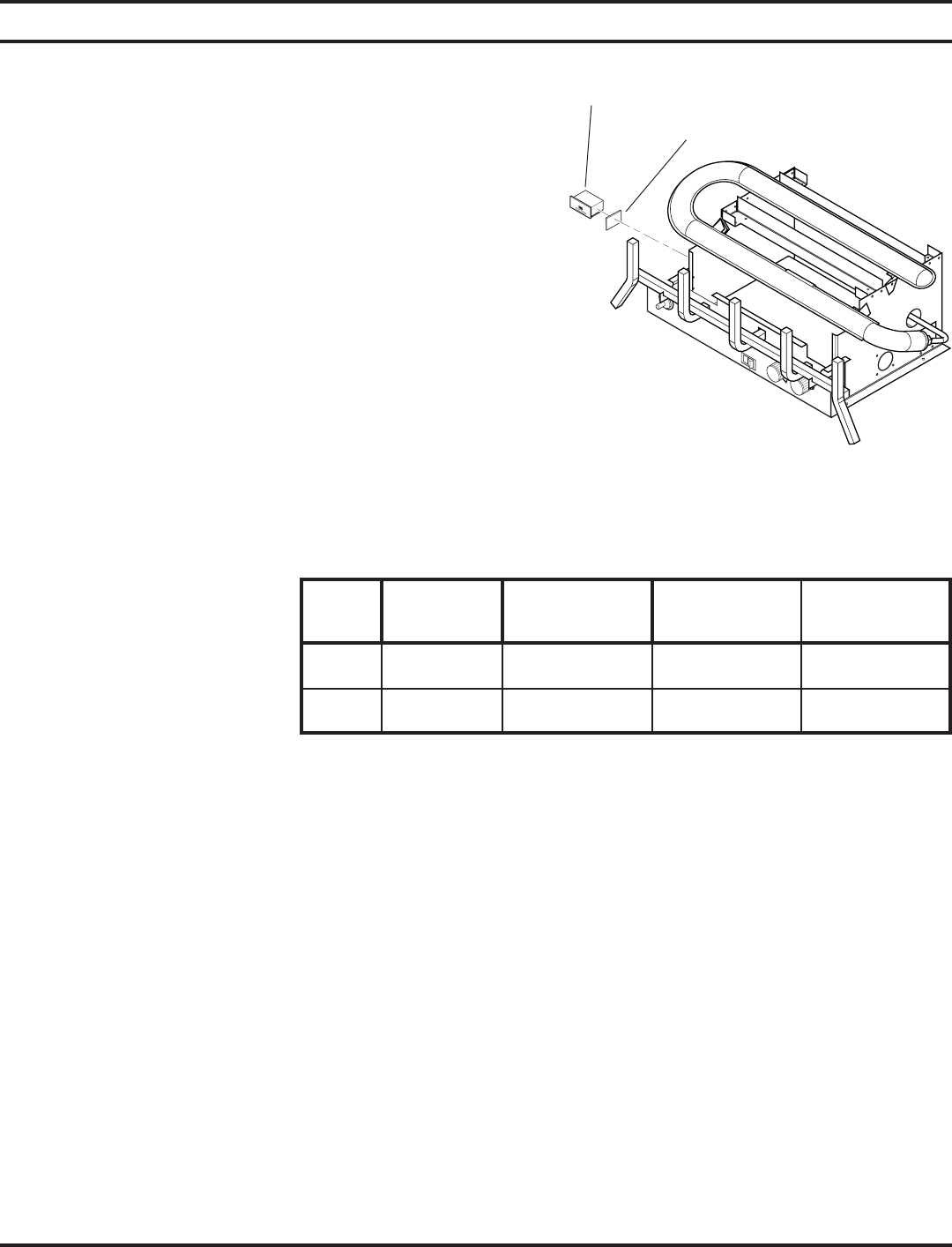
Figure 17 - Installing Remote Receiver
Velcro Pads
Remote
Receiver
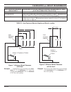
CHECK
TEST
TO TEST
CONNECT
METER LEADS
TO TERMINALS
ON/OFF
CONTACTS
METER READING
SHOULD BE
A
COMPLETE
SYSTEM
2 & 3 CLOSED MINIMUM 175mV
B
THERMOPILE
OUTPUT
1 & 2 OPEN MINIMUM 500mV
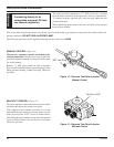
CONNECTING OPTIONAL REMOTE RECEIVER
FOLLOW INSTRUCTIONS SUPPLIED WITH THE REMOTE.
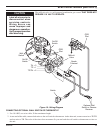
1. Connect the wires to the two .25" male connectors located on the
left side of the valve when facing the unit (See Figure 16, page
19). Do not let wire touch grate or burner.
2. Stick velcro pads with self-adhesive backing to the right side of
remote receiver and to the left side of the unit. See Figure 17.
3. Attach remote receiver with velcro pads. Control switch must face
forward.
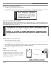
NOTE: Heat reduces battery life. You can protect the
receiver and extend battery life by mounting the receiver in
a wall or other location outside the fireplace.