12 46D0550
CHECKING GAS PRESSURE AND CONNECTING REMOTE RECEIVER
The heater gas inlet connection is 3/8" NPT at the valve. The
inlet is located on left side of stove. Remove front control plate
to better access the inlet.
When tightening up the joint to the valve, hold the valve securely
with a wrench to prevent movement.
Test all gas joints from the gas meter to the heater valve for
leaks using a gas analyzer or soap and water solution after completing connection. DO NOT USE AN OPEN FLAME.
Check the gas pressure with the appliance burning and the control set to HIGH.
Connecting directly to an unregulated
propane/L.P.G. tank can cause an
explosion.
WARNING
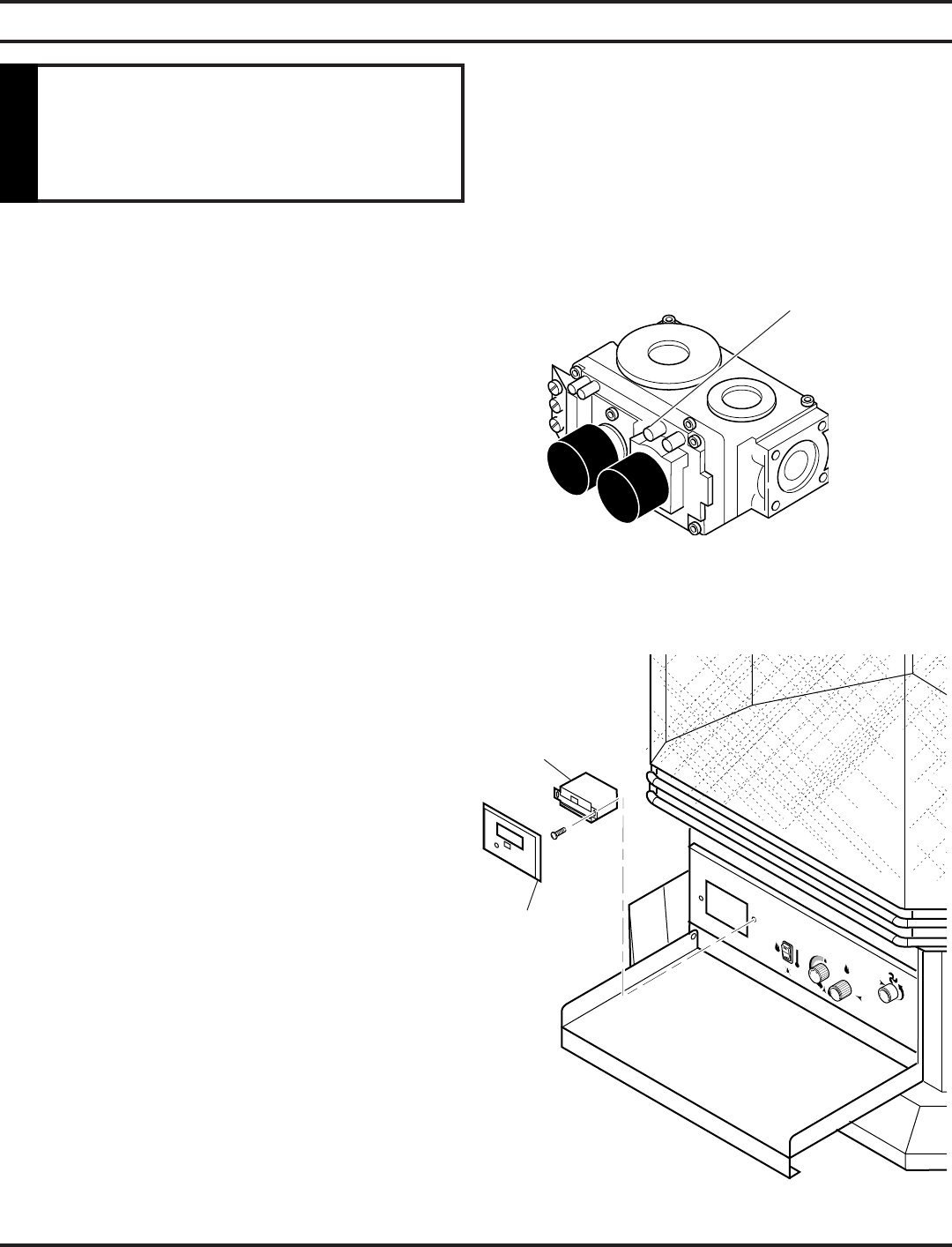
MILLIVOLT CONTROL (FIGURE 5)
The valve regulator controls the burner pressure which should
be checked at the pressure test point.
If outlet pressure is low, check inlet pressure against data plates
or manual.
Turn captured slotted screw counter clockwise 2 or 3 turns and
then place tubing to pressure gauge over test point (Use test
point “OUT” closest to control knob). After taking pressure
reading, be sure and turn captured screw clockwise rmly to
re-seal. Do not over torque. Check for gas leaks.
NOTE: Remove control panel to access gas valve.
Ignitor battery module is located on back of panel.
Figure 5 - Pressure Test Point Location
Milli-Volt Control
Test Port “OUT”
CONNECTING REMOTE RECEIVER
1. Remove cover on control panel to show opening for
remote receiver. See Figure 6.
2. Cut cable to length (approximately 12") for placement in
the replace.
3. If wires are not stripped, strip back
1
/4" of the insulation
from free end of each wire. Do not cut off wire connec-
tor.
4. Connect two .25 female connectors to the wires at free
end of the cable.
5. Insert the wire connector into the receiver. If remote does
not have plug-in connector, strip back
1
/4" of insulation.
Insert wires into terminal and tighten screws.
6. Connect the connectors to the two .25" male connectors
located on the left side when facing the unit (Figure 6).
Do not let the wires touch the grate or burners.
7. Slide remote receiver in the opening of control panel.
Use two screws provided to attach remote receiver to the
control panel. See Figure 6.
8. Replace cover with cover supplied with remote. See
Figure 6.
Figure 6 - Installing Remote Receiver
Remote
Receiver
Cover
NOTE: Do not place remote in combustion chamber.


