71D0532 9
L
J
K
5 7/16"
G
F
D
E
C
34 1/2"
H
A
B
I
1 1/4"
21 3/4"
6"
1 5/16"
2 1/2"
GENERAL INSTALLATION INFORMATION
In planning the installation for the fireplace it is necessary to determine where the unit is to be installed and whether optional
accessories are desired. Gas supply piping should also be planned. The following steps represent the normal sequence of
installation. Each installation is unique, however, and might require a different sequence.
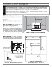
1. Position fireplace in desired location. Refer to the “Loca-
tion of Fireplace” and “Clearances and Height Require-
ments,” and “Firebox Framing” sections found in this
manual. Note: Be sure all packing material has
been removed from underside of the unit.
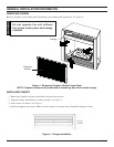
2. Install canopy and logs per instructions found in
this manual. The canopy MUST be installed for safe
operation of the unit.
3. Field wire main power supply to units with fan kit.
Refer to the “Electrical Section” found in this manual.
(Electrical connections should only be performed by an
experienced, licensed certified tradesman).
4. Install optional ON/OFF kit on units with milli-volt
control. Refer to installation instructions included with
the kit and also refer to the “Electrical Wiring” section
found in this manual.
5. Plumb gas line. Refer to the “Connecting the Gas”
section found in this manual. (Gas connections should
only be performed by an experienced, licensed / certified
tradesman).
6. Complete finish wall material and/or surround.
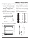
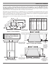
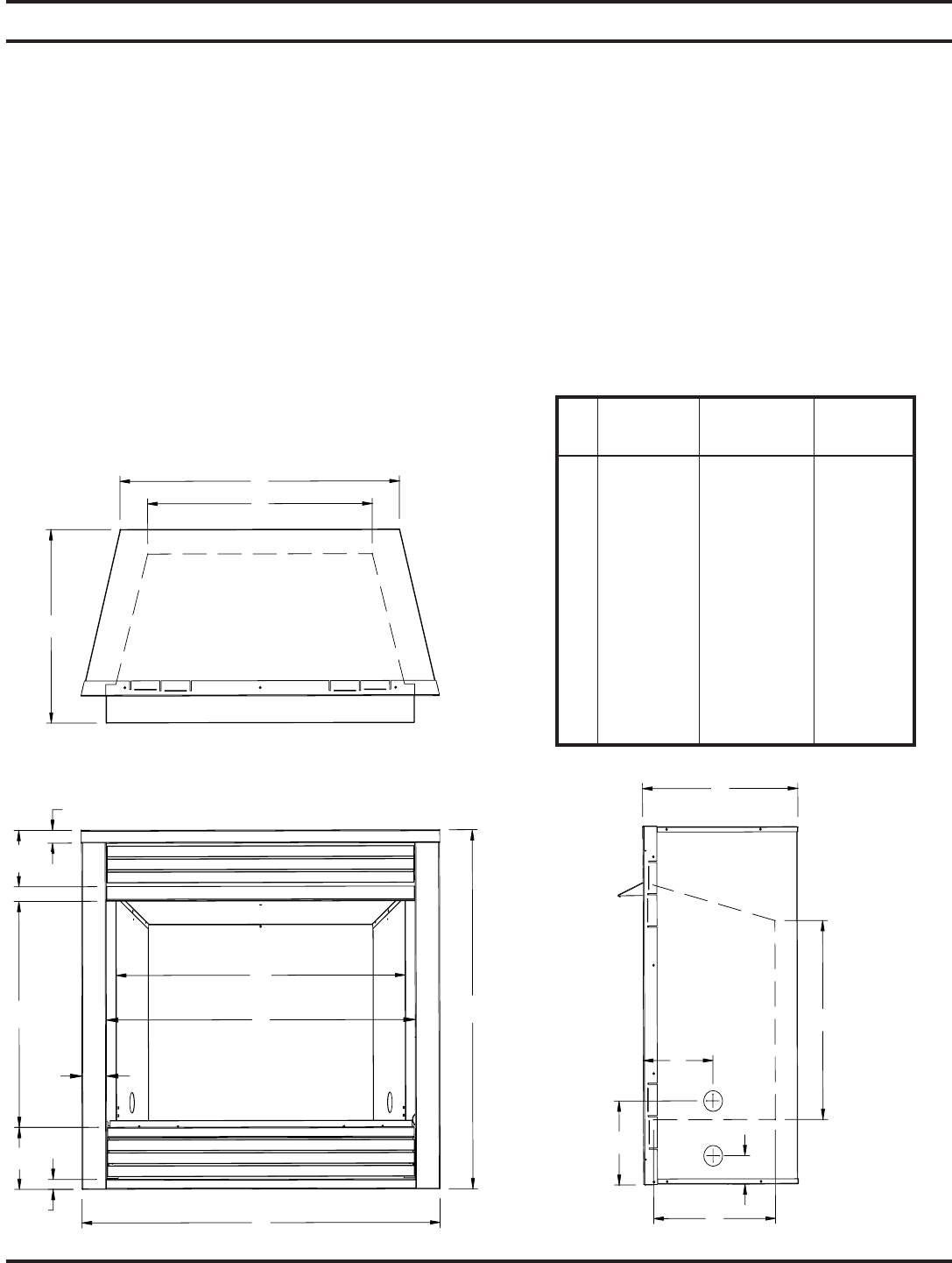
Figure 2 - Firebox Dimensions with Screen and Log Sets
DFS32NVC DFS36NVC DFS42NVC
DFS32PVC DFS36PVC DFS42PVC
A 37" 41" 47"
B 32" 36" 42"
C 16" 18" 18"
D 29" 32" 38"
E 18⅝" 20⅝" 20⅝"
F 23⅜" 27⅜" 33⅜"
G 13¼" 15¾" 15¾"
H 18" 17⅝" 17⅝"
I 29⅞" 34" 40"
J 7⅛" 9¾" 9¾"
K 8" 8¼" 8¼"
L 2¾" 2¼" 2¼"
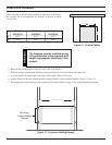
1 ¼"
5
7
/16"
21 ¾"
2 ½"
1
5
/16"
6"
34 ½"


