58D6056
15
CSDV Series Direct Vent Gas Stove
1. Determine the route your horizontal venting will take.
The location of the horizontal vent termination on
the exterior wall must meet all local and national building
codes.
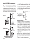
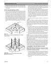
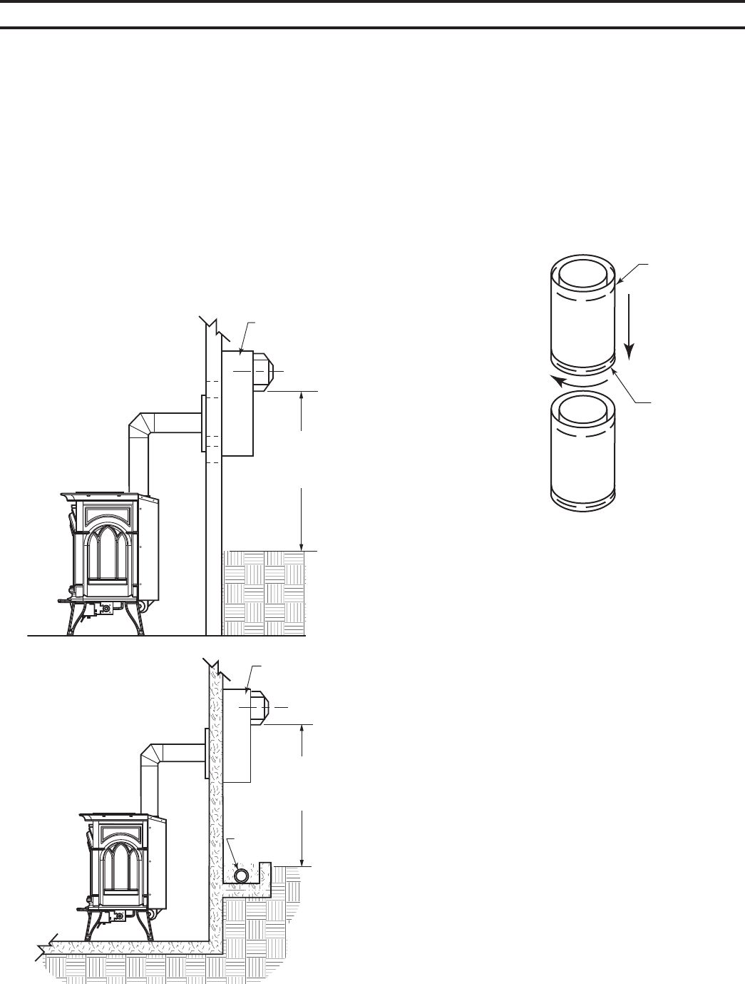
Snorkel terminations are available for terminations requir-
ing a vertical rise on the exterior of the building. Figures 14
and 15. Follow the same installation procedures used for
standard horizontal terminations. If installing the snorkel
termination below grade (basement applications), you must
provide proper drainage to prevent water from entering the
snorkel termination. Figure 13. Do not back fill around the
snorkel termination.
ST1137
snorkel install
12”
(305 mm)
Minimum
Snorkel
Figure 14 -
Snorkel Termination
ST1137
12”
(305 mm)
Minimum
ST1138
snorkel drainage
Snorkel
Adequate
Drainage
Figure 15 -
Snorkel Termination
with Drainage Pipe
ST1138
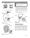
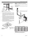
2. Rigid vent pipes and fittings have special twist-lock
connections. Assemble the desired combination of pipe
and elbows to the appliance adaptor with pipe seams
oriented towards the wall or floor.
Twist-lock Procedure: The female ends of the pipes
and fittings have three locking lugs (indentations).
These lugs will slide straight into matching slots on
the male end of adjacent pipes and fittings. Push the
pipe sections together and twist one section clockwise
approximately one-quarter turn until the sections are
fully locked. Figure 16.
FP1953
rigid pipe
Female Locking
Lugs
Male Slots
FP1953
Figure 16 -
Rigid Vent Pipe Connections
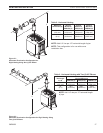
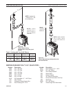
3. Attach vent pipe assembly to the stove. Set stove in
front of its permanent location to insure minimum clear-
ances. Mark the wall for a 9Z\x" (241 mm) square hole
(for noncombustible material such as masonry block or
concrete, a 7Z\x" [190 mm] diameter hole is acceptable).
Figure 17. The center of the hole should line up with the
center line of the horizontal rigid vent pipe. Cut a 9Z\x" x
9Z\x" (241 x 241 mm) square hole through combustible
exterior wall (7Z\x" [190 mm] diameter hole if noncom-
bustible). Frame as necessary. Figure 17
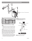
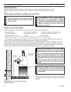
4. Apply a bead of non-hardening mastic around the
outside edge of vent cap. Position the vent cap in the
center of the 7Z\x" (190 mm) or 9Z\x" (241 mm) hole on the
exterior wall with the word “UP” on the vent cap facing
up. Insure proper clearance of 1" to combustibles is
maintained. Attach the vent cap with four wood screws
supplied. Figure 18
For vinyl siding, stucco, or wood exterior use vinyl siding
standoffs between vent cap and exterior wall. The vinyl
siding standoff prevents excessive heat from melting the
vinyl siding material. Bolt the vent cap to the standoff. Apply
non-hardening mastic around outside edge of the standoff
instead of the vent cap assembly. Use wood screws pro-
vided to attach the standoff. Figure 19
Replace the wood screws with appropriate fasteners
for stucco, brick, concrete, or other types of siding.


