


69D0023 19
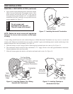
9
1
/2"
(241mm)
9
1
/2"
(241mm)
3
3
/4"
(92mm)
7
1
/2"
(190mm)
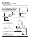
Maximum
20"
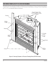
Top View Flat Installation
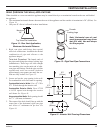
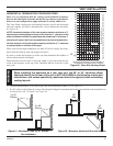
REAR (THROUGH THE WALL) APPLICATIONS
When installed as a rear vent unit this appliance may be vented directly to a termination located on the rear wall behind
the appliance
• The maximum horizontal distance between the rear of the appliance and the outside of termination is 20" (508 m). See
Figure 14.
• Only one 45° elbow is allowed in these installations.
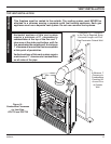
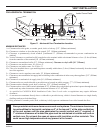
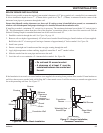
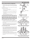
VENTING INSTALLATION
1. Rigid vent pipes and fittings have special
twist-lock connections. Assemble the desired
combination of pipe and elbows to the
appliance adaptor.
Twist-lock Procedure: The female ends of
the pipes and fittings have three locking lugs
(indentations). These lugs will slide straight
into matching slots on the male end of adja-
cent pipes and fittings. Push the pipe sections
together and twist one section clockwise
approximately one-quarter turn until the sec-
tions are fully locked. See Figure 15.
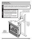
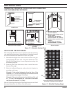
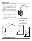
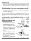
2. Locate and cut the vent opening in the wall.
For combustible walls first frame in opening.
Combustible Interior Walls: Cut a 11
1
/2"H x
9
1
/2" W hole through the interior wall.
Combustible Exterior Walls: Cut a 9
1
/2"H
x 9
1
/2"W square hole through the exterior
wall frame. See Figure 16.
Noncombustible Walls: Hole opening should
be 7
1
/2" (190 mm) in diameter.
3. The center of the hole should line up with the
center line of the horizontal rigid vent pipe
end. Allow
1
/4" minimum rise per foot. See
Figure 16.
Figure 14 - Rear Vent Application,
Maximum Horizontal Distance
Figure 16 - Exterior Wall Framing Dimensions
Note: Horizontal runs of vent
must be supported every three
feet (914 mm). Use wall straps
for this purpose.
Figure 15 - Rigid Vent Pipe Connections
Female
Locking Lugs
Male Slots