


22
53D9051. Rev 1 03/03
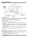
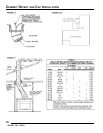
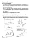
COMBUSTION AIR ASSEMBLY
MODEL OAC4 COMBUSTION AIR ASSEMBLY
1. Remove the cover cap from the 4 inch outlet opening location on the left or right outside surface of the
fireplace. DO NOT REMOVE THE COVER IF THE OUTSIDE AIR WILL NOT BE CONNECTED.
2. Fasten the (4 inch) starting collar over the hole on the left or right side of the fireplace with the four sheet
metal screws provided. (see figure 22).
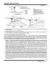
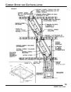
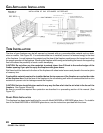
3. Cut a 6 inch diameter opening for model OAC4 in the outside wall covering where the model OAC4 outside
grille is to be located. (See figure 24).
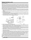
4. Select and cut a piece of duct of sufficient length to attach to the fireplace and protrude at least three
inches beyond the face of the wall to which the OAC4 inlet air box assembly will be attached. The duct may
be cut with a standard pocket knife. (Use FP-4-U duct for maximum efficiency and safety) Do not use a
combustible duct. Always use UL listed Class 0 or 1 duct material.
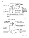
5. If the duct is the insulated type, push the insulation back from one end of the duct approximately two
inches. (See figure 25)
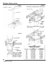
6. Slip the exposed end of the duct over the flange tube of the fireplace.
7. Place the duct clamp around the exposed end of the aluminum duct.
8. Slip the band through the housing, then pull the band tight around the duct.
9. Snap the band locking screw down and tighten it with a screwdriver or nutdriver. (see figure 25)
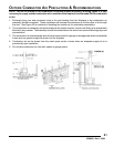
10.Nail or screw the combustion air assembly to the surface of the wall.
NOTE: If the wall covering is brick or stone, use appropriate masonry fasteners. Mount the combustion air
assembly with “TOP” upward to prevent rain from entering the assembly. Be sure the 6 inch diameter
opening around the air duct is sealed with insulation material to prevent cold air from entering through the
wall. If it is necessary to splice the duct, a model 403 duct connector should be installed as described by
figure 26.