


2
OPERATIONS
INSTALLATION INSTRUCTIONS
DRY TEST
ATTENTION: To insure proper operation, before
installing the faucet, a “DRY TEST” is
recommended.
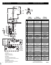
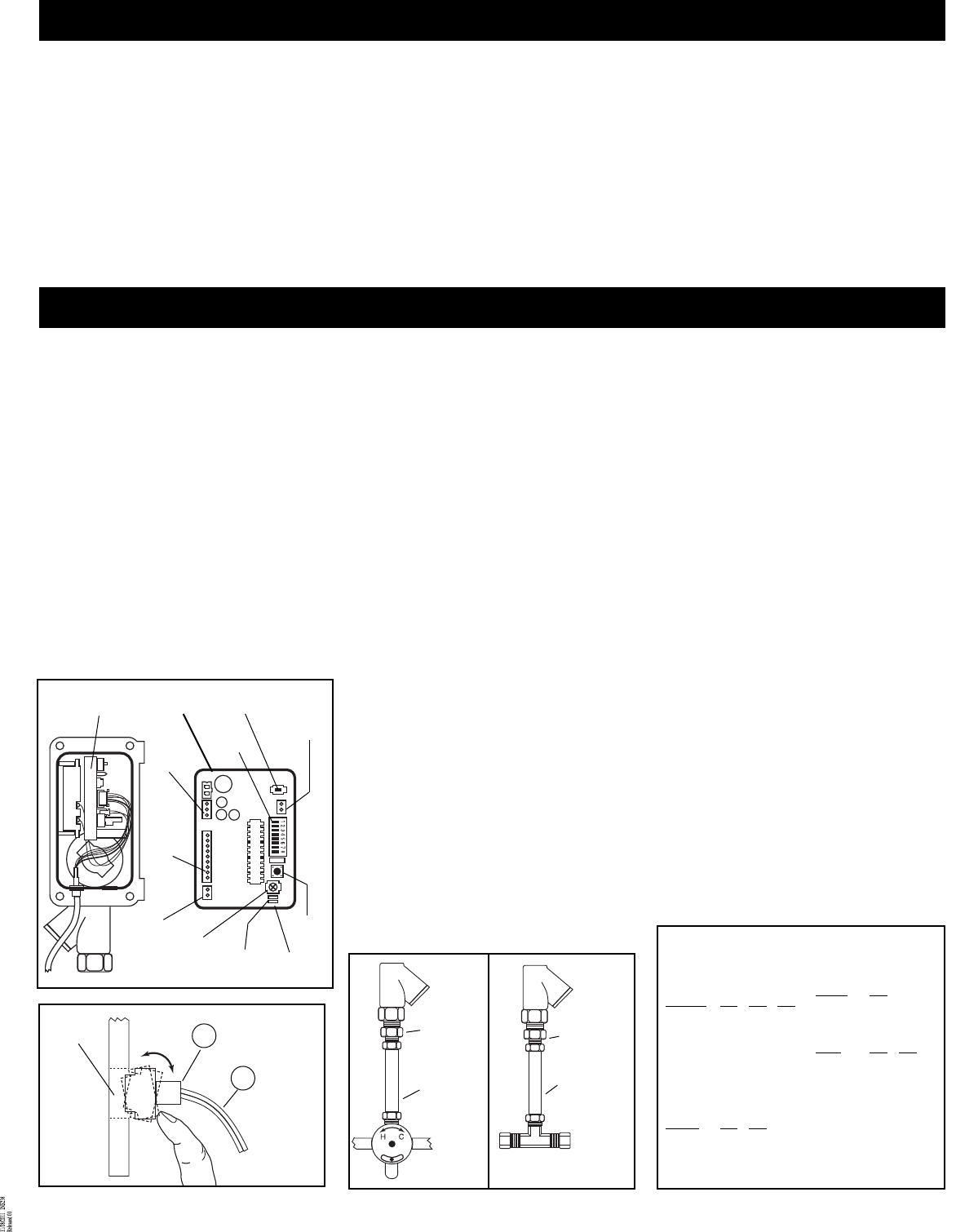
1. Take off the control box lid (11) by removing
screws (12) with hex wrench.
2. Connect the sensor eye connector (22) at the
end of the sensor eye cable (21) onto the
circuit board (28) inside the control box (9)
Refer to illustration “A”.
3. Slide battery housing out of control box (9)
and install batteries (included) and slide
battery housing back into control box (9).
Insert the battery housing connector onto the
circuit board (28). The lights on the circuit
board should blink red/green/red.
4. Place your hand in front of the sensor (27) to
operate the faucet and listen for a “clicking”
sound.
5. Remove your hand and listen for a softer
“clicking” sound. The “clicking” sounds
indicate that the faucet is working properly. If
there is no light or sound, please contact
Moen at 1-800-289-6636.
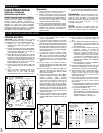
6. The sensors are equipped with angular
adjustments. The factory setting is in the
center or straight position from the faucet.
Adjustment is most easily performed before
the faucet is installed. The adjustment is
located inside the faucet body (1) behind the
LED indicator light (27) Refer to illustration
“B”.
7. If you are ready to install the faucet,
disconnect the sensor eye connector (22) at
the end of the sensor eye cable (21) from the
circuit board (28).
8. Slide gasket (3) over sensor eye cable and
onto faucet.
9. Set faucet on sink and install mounting
washer (5) and mounting nut (6). Tighten
mounting nut (6) to secure the faucet to the
sink.
10. Attach compression reducer (30) to the
supply rod (4). Also attach compression
adapter (14) to the solenoid valve outlet.
11. Connect the sensor eye connector (22) at the
end of the sensor eye cable (21) onto the
circuit board (28). Properly seat both the
sensor eye cable seal and cable into the
control box slot on the left. Reinstall control
box lid (11) and tighten screws (4) to insure
the control box is water-resistant. NOTE:
make sure that the rubber seal plug is in
installed in the AC adapter control box slot
(on the right).
12. Connect 3/8” copper tube (supplied) between
the supply rod (4) and the solenoid valve
(20). Tighten compression fittings.
13. Insert white nylon washer (8) into swivel nut
on filter body inlet.
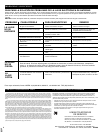
14. A) For standard (pre-tempered or cold water)
installation, attach water supply to inlet of
in-line filter/check valve body.
B) If a tempered water installation is needed,
attach mixing/check valve (optional) to the
inlet of in-line filter/check valve body.
Connect water supply lines to
mixing/check valve. Refer to illustration
“C”. NOTE: USE THREAD SEAL TAPE
FOR ALL THREADED CONNECTIONS.
C) Refer to Illustration D for the optional
mixing tee installation.
15. Mount faucet spout (15) to faucet body (1)
and secure with spout o-ring (17) and spout
nut (16).
16. Turn on water and check for leaks. Place
hand in front of sensor to activate water.
Remove hands and the water should stop. If
not, refer to troubleshooting guide.
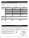
17. For timing adjustments, refer to instructions
on the inside of the control box lid. Refer to
Illustration E.
A) Note: Be sure to depress the re-set
button, located on the circuit board, after
each adjustment.
B) The factory settings are:
Sensor Distance Adjustment =
approximately 3.5 inches from the lens
Time Delay to shut-off after hands are
removed = 1 sec seconds
Auto – shutoff = 30 seconds
D
Sensor
Lens
Sensors
26
Sensor
Eye Cable
21
Optional
Supply
Tube
provided
by
installer
B
Compression
adapter
Optional
Supply
Tube
provided
by installer
Compression
adapter
C
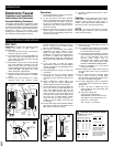
Electronic Faucet
Operation and Installation
Instructions for Electronic
Faucets-Battery-Powered
The battery-powered faucet is designed for ease
of installation and provides a reliable, convenient,
economical and sanitary system for high-volume
users, such as hospitals, transportation terminals,
restaurants, schools, sports arenas, office
buildings and municipalities. It can be installed by
one tradesman without electrical hook-up.
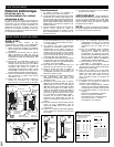
Operation:
1. The faucet operates by emitting a continuous
infared beam from the sensor.
2. As the user enters the beam’s effective
range, a red light flashes one time to alert the
user that the faucet will operate. As long as
the user is in the beam’s range, the beam is
reflected into the receiver circuitry and the
system will operate.
3. When the user exits out of range, the sensor
sends a signal to the solenoid for closure.
The sensor then automatically resets and is
ready for the next user.
4. Low battery indicator light comes on when
battery is low.
Caution: Avoid installing the faucet where
sensor faces a stainless steel wall or other
reflective surface within the active range of
sensors. Avoid facing another infrared sensor. It
may cause faucet to activate unnecessarily.
NOTE: The reset button must be pressed
after changing the battery in order to ensure the
faucet functions properly.
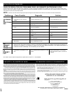
E
CONTROL BOX INSTRUCTIONS
ADJUSTMENTS: (DIP Switches):
1. Shut-off time delay
after hands are removed:
Time Delay SW1 SW2 SW3
1 Sec on on on
2 Sec on on off
3 Sec on off on
4 Sec on off off
5 Sec off on on
6 Sec off on off
7 Sec off off on
8 Sec off off off
2. Auto Time-Out Feature:
Time-Out SW4 SW5
0 Sec on on
15 Sec on off
30 Sec off on
60 Sec off off
3. Sensor Distance:
Distance SW6
3.5 – 12" on
10 – 24" off
4. Faucet Setting:
Setting SW7 SW8
Faucet on off
SENSOR DISTANCE ADJUSTMENT
(SDA): Preset at factory. If
adjustment is needed; Locate
potentiometer with Phillips Head
adjuster screw. Turn adjuster screw
clockwise to increase SDA, counter
clockwise to decrease SDA.
AC/DC switch
Sensor
distance
adjustor
Reset
button
DIP
switches
Green
LED
DC receptor
Sensor
eye
cable pin
receptor
A
Circuit board
side view
Circuit board
front view
AC
receptor
Solenoid
pin
receptor
Red
LED