


6-3 PIPE CONNECTION
Note:
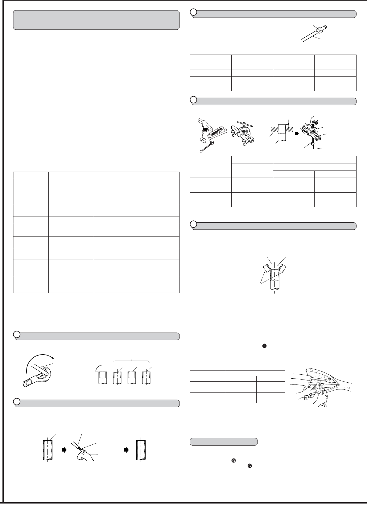
Fasten a flare nut with a torque wrench as specified in the table below.
When fastened too tight, a flare nut may broken after a long period and cause a leakage
of refrigerant.
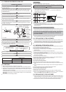
1 Indoor unit connection
Connect both liquid and gas pipings to indoor unit.
•
Apply a thin coat of refrigeration oil on the seat surface of pipe.
•
For connection first align the center, then tighten the first 3 to 4 turns of flare nut.
•
Use tightening torque table below as a guideline for indoor unit side union joint
section, and tighten using two wrenches. Excessive tightening damages the flare
section.
Pipe diameter
Tightening torque
N·m kgf·cm
ø6.35 mm 13.7 to 17.7 140 to 180
ø9.52 mm 34.3 to 41.2 350 to 420
ø12.7 mm 49.0 to 56.4 500 to 575
ø15.88 mm 73.5 to 78.4 750 to 800
2 Outdoor unit connection
Connect pipes to stop valve pipe joint of the outdoor unit in the same manner applied for
indoor unit.
•
For tightening, use a torque wrench or spanner and use the same tightening torque
applied for indoor unit.
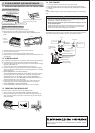
INSULATION AND TAPING
1 Cover piping joints with pipe cover.
2 For outdoor unit side, surely insulate every piping including valves.
3 Using piping tape
, apply taping starting from the entry of outdoor unit.
•
Stop the end of piping tape with tape (with adhesive agent attached).
•
When piping have to be arranged through above ceiling, closet or where the
temperature and humidity are high, wind additional commercially sold insulation for
prevention of condensation.
6. INDOOR/OUTDOOR UNIT CONNECTION
FINISHING AND TEST RUN
INSTALLATION INFORMATION FOR THE AIR CONDI-
TIONER WITH R410A REFRIGERANT
•
This room air conditioner adopts an HFC refrigerant (R410A) which will never destroy
the ozone layer.
•
Pay particular attention to the following points, though the basic installation
procedure is same as that for R22 air conditioners.
1 As R410A has a working pressure approx. 1.6 times as high as that of R22, some
special tools and piping parts / materials are required. (Refer to the table below.)
2 Take sufficient care not to allow water and other contaminations to enter the
R410A refrigerant during storage and installation, since it is more susceptible to
contaminations than R22.
3 For refrigerant piping, use clean, pressure-proof parts / materials specifically
designed for R410A. (Refer to 2. Refrigerant piping.)
4 Composition change may occur in R410A since it is a mixed refrigerant. When
charging, charge liquid refrigerant to prevent composition change.
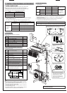
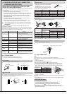
6-1 Tools dedicated for the air conditioner with R410A
refrigerant
The following tools are required for R410A refrigerant. Some R22 tools can be
substituted for R410A tools.
The diameter of the service port on the stop valve in outdoor unit has been changed to
prevent any other refrigerant being charged into the unit. (Cap size has been changed
from 7/16 UNF with 20 threads to 1/2 UNF with 20 threads.)
R410A tools Can R22 tools be used? Description
R410A has high pressures beyond the meas-
urement range of existing gauges.
Gauge manifold No Port diameters have been changed to prevent
any other refrigerant from being charged into the
unit.
Charge hose No
Hose material and cap size have been changed
to improve the pressure resistance.
Gas leak detector No Dedicated for HFC refrigerant.
Torque wrench
Yes 1/4 and 3/8
No 1/2 and 5/8
Flare tool Yes
Clamp bar hole has been enlarged to reinforce
the spring strength in the tool.
Flare gauge New
Provided for flaring work (to be used with R22
flare tool).
New
Provided to prevent the back flow of oil. This
adapter enables you to use existing vacuum
pumps.
New
It is difficult to measure R410A with a charging
cylinder because the refrigerant bubbles due to
high pressure and high-speed vaporization.
No: Not substitutable for R410A Yes: Substitutable for R410A
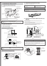
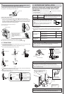
6-2 FLARING WORK
•
Main cause of gas leakage is defect in flaring work.
Carry out correct flaring work in the following procedure.
1
Pipe cutting
•
Cut the copper pipe correctly with pipe cutter.
2
Burrs removal
•
Completely remove all burrs from the cut cross section of pipe.
•
Put the end of the copper pipe to downward direction as you remove burrs in order to
avoid to let burrs drop in the piping.
Copper pipe
Good
No good
Tilted
Uneven
Burred
Burr
Copper pipe
Spare
reamer
Pipe
cutter
Flare nut
Copper pipe
Smooth all around
Even length
all around
Inside is shining without any scratches.
90°
Electronic scale
for refrigerant
charging
Vacuum pump
adaptor
3
Putting nut on
•
Remove flare nuts attached to indoor and outdoor
units, then put them on pipe having completed
burr removal.
(not possible to put them on after flaring work)
•
Flare nut for R410A pipe differs from R22 pipe.
Refer to the following table for detail.
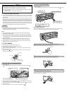
4
Flaring work
•
Carry out flaring work using flaring tool as shown below.
•
Firmly hold copper pipe in a die in the dimension shown in the table above.
5
Check
•
Compare the flared work with figure below.
•
If flare is noted to be defective, cut off the flared section and do flaring work again.
mm inch R410A R22
ø6.35 1/4 17 17
ø9.52 3/8 22 22
ø12.7 1/2 26 24
ø15.88 5/8 29 27
A (mm)
Outside diameter Conventional flare tool
Clutch type Wing nut type
ø6.35 mm 0 to 0.5 1.0 to 1.5 1.5 to 2.0
ø9.52 mm 0 to 0.5 1.0 to 1.5 1.5 to 2.0
ø12.7 mm 0 to 0.5 1.0 to 1.5 2.0 to 2.5
ø15.88 mm 0 to 0.5 1.0 to 1.5 2.0 to 2.5
Flare tool for R410A
clutch type
A
Die
Copper pipe
Flare nut
Die
Copper pipe
York
Flaring tool
Wing nut type
Clutch type