


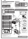
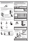
10 m or less
15 m or less
25 m or less
Power supply cord
Specification
Indoor and Outdoor
connecting wire
Specification
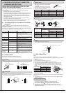
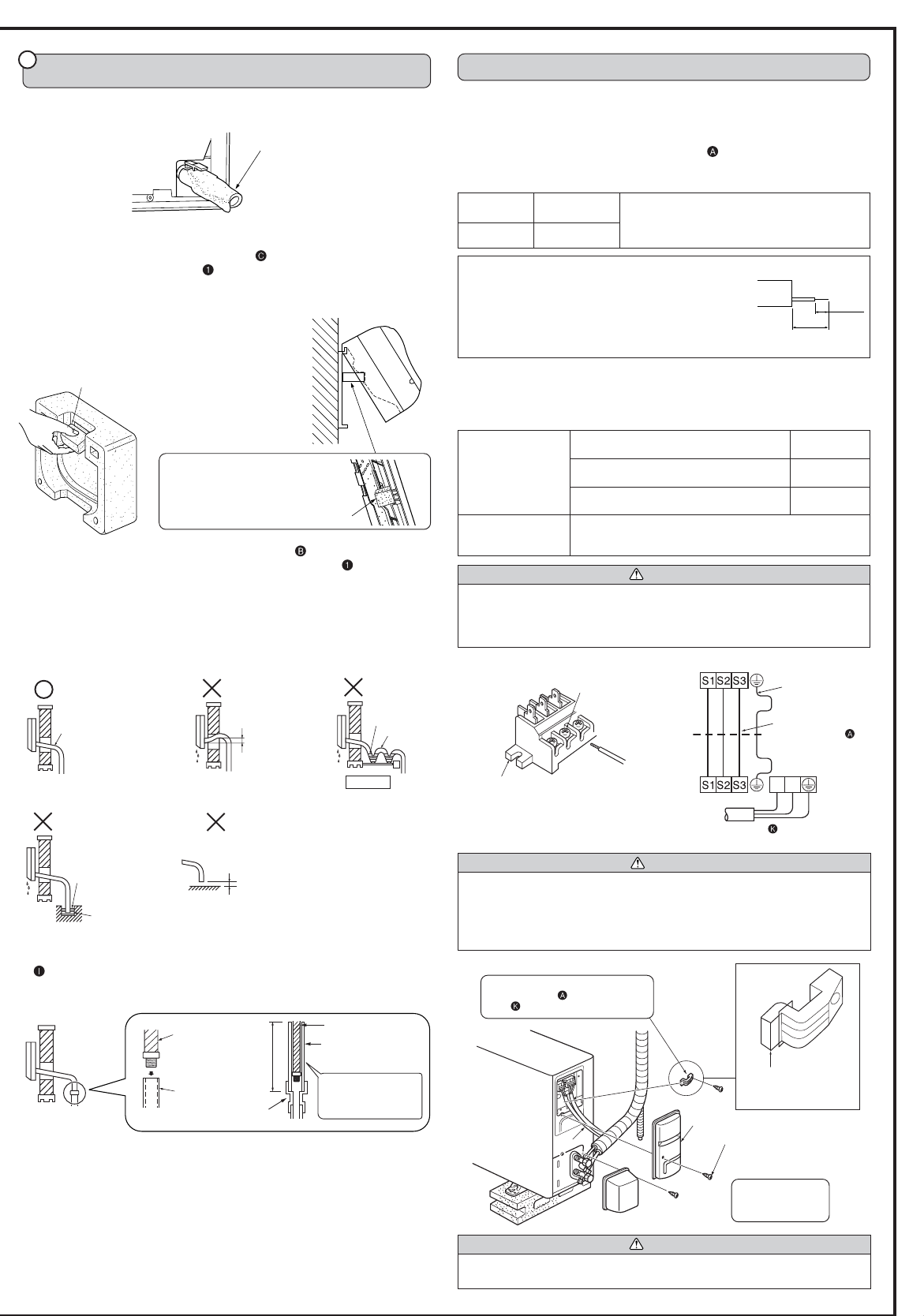
5. OUTDOOR UNIT INSTALLATION
INDOOR/OUTDOOR UNIT CONNECTING WIRE CON-
NECTION AND OUTDOOR POWER SUPPLY CORD
CONNECTION
•
Connect the indoor/outdoor unit connecting wire from the indoor unit correctly
on the terminal block.
•
For future servicing, give extra length to connecting wire.
Rated Voltage Breaker capacity
230 V 20 A
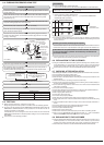
•
Peel off both ends of connecting wire (extension wire).
When too long, or connected by cutting off the middle,
peel off power supply wire to the size as shown in the
right.
•
Be careful not to contact connecting wire with piping.
•
Make earth wire a little longer than the others.
(more than 35 mm)
•
For the indoor/outdoor unit connecting wires, be sure to use the ones in compliance
with the standards.
•
Be sure to push the core until it is hidden and pull each cable to make sure that it
is not pulled up incomplete insertion may cause a risk of burning the terminal
blocks.
CAUTION
•
Use care not to make mis-wiring.
•
Firmly tighten the terminal screws to prevent them from loosening.
•
After tightening, pull the wires lightly to confirm that they do not move.
•
If the connecting wire is incorrectly connected to the terminal block, the unit
does not operate normally.
Connect to the supply terminals and leave a contact
separation of at least 3 mm at each pole to discon-
nect the source power pole. (When the power switch
is shut off, it must disconnect all poles.)
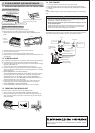
Drain hose
4
Insert the drain hose into the section to which the drain hose is
to be attached at the rear right of the indoor unit.
Insert the drain hose fully into the drain pan. Check if the hose is hooked securely to
the projection of its inserting part at the drain pan.
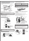
INDOOR UNIT INSTALLATION
•
Insert the drain hose into the wall hole sleeve , and hook the upper part of
indoor unit on the installation plate
. Then, move the unit to the very edge of the
left side for putting the piping easily in the back space of the indoor unit. After that,
cut the part of packing material (spacer assembly) to hook it on the back rib and
lift the indoor unit as shown in the figure below.
•
Connect the refrigerant piping with the extension pipe .
•
Thrust the lower part of the indoor unit into the installation plate .
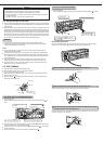
4-7 DRAIN PIPING
•
If the extension drain hose has to pass through a room, be sure to wrap it with
commercially sold insulation.
•
The drain hose should point downward for easy drain flow. (Fig. 1)
Do not make drain piping as shown in Fig. 2 to 5.
Spacer assembly
Securely attach the spacer
assembly in the concave part
of the rib, taking care its
direction is correct as shown in
the right.
Spacer
Cut part of packing material (spacer assembly) to
hook it on the back rib.
WARNING
•
A means for disconnection of the supply with an isolation switch, or similar
device, in all active conductors shall be incorporated in the fixed wiring.
•
Never cut the power cord and connect it to other wires.
It may cause a fire.
Loosen terminal screw.
Terminal block
Lead wire
<Connection details>
WARNING
Be sure to attach the service panel of the outdoor unit securely. If it is not attached
correctly, it could result in a fire or an electric shock due to dust, water, etc.
Remove two fixing
screws to open the
service panel.
Service panel
Fixing screws
Be sure to put the left
portion into the square
hole of the service panel.
Be sure to fix the indoor/outdoor unit
connecting wire
and power supply
cord using this cord clamp.
Valve cover
35 mm
15 mm
3-core 2.5 mm
2
or more, in conformity with
Design 245 IEC 57.
3-core 4.0 mm
2
or more, in conformity with
Design 245 IEC 57.
Cable 4-core 1.0 mm
2
, in conformity with
Design 245 IEC 57.
3-core 6.0 mm
2
or more, in conformity with
Design 245 IEC 57.
Power supply cord 3-core
Indoor terminal block
Outdoor terminal block
Indoor/outdoor unit
connecting wire
4-core 1.0 mm
2
L
N
Earth wire
(green/yellow)
Downward slope
Water
leakage
Do not raise.
Water
leakage
Accumulated
drain water
Waving
(Fig. 1) (Fig. 2)
Water
leakage
Tip of drain
hose dipped
in water.
Ditch
Soft hose
I.D.
15 mm
Drain hose
Less than
50 mm gap
(Fig. 3)
•
If the drain hose provided with the indoor unit is too short, connect it with drain hose
that should be provided at your site. (Fig.6)
•
When connecting the drain hose to the hard vinyi chloride pipe, be sure to insert it
securely into the pipe. (Fig.7)
Air
(Fig. 4) (Fig. 5)
(Fig. 6)
(Fig. 7)
70 cm
or more
Different-
diameter joint
Drain hose
Hard vinyl chloride pipe
I.D. 30 mm
Be sure to insert the
drain hose securely
into the pipe.