


5
5. Refrigerant piping work
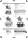
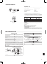
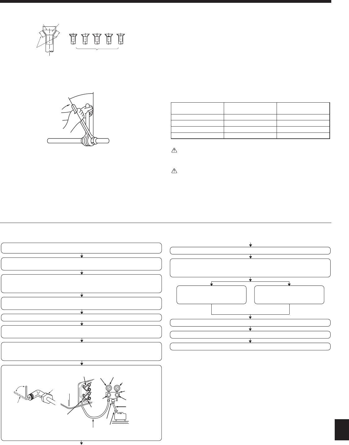
5.2.5. Check (Fig. 5-7)
• Comparethearedworkwithagureinrightsidehand.
•
Ifareisnotedtobedefective,cutoffthearedsectionanddoaringworkagain.
a Smooth all around fScratchonaredplane
b Inside is shining without any scratches g Cracked
c Even length all around h Uneven
d Too much i Bad examples
e Tilted
• Apply a thin coat of refrigeration oil on the seat surface of pipe. (Fig. 5-8)
•
Forconnectionrstalignthecenter,thentightentherst3to4turnsofarenut.
• Use tightening torque table below as a guideline for indoor unit side union joint
section,andtightenusingtwowrenches.Excessivetighteningdamagestheare
section.
Copper pipe O.D.
(mm)
Flare nut O.D.
(mm)
Tightening torque
(N·m)
ø6.35 17 14 - 18
ø9.52
22 34 - 42
ø12.7 26
49 - 61
ø15.88 29 68 - 82
Warning:
When installing the unit, securely connect the refrigerant pipes before start-
ing the compressor.
Warning:
Be careful of ying are nut! (Internally pressurized)
Remove the are nut as follows:
1. Loosen the nut until you hear a hissing noise.
2. Do not remove the nut until the gas has been completely released (i.e.,
hissing noise stops).
3.
Check that the gas has been completely released, and then remove the nut.
Fig. 5-7
Fig. 5-8
1
0
/
2 3 4 5 6
7
B
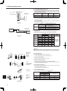
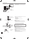
5.5. Purging procedures leak test
*Close
*Open
Hexagonal wrench
Stopvalve
*4 to 5 turns
Stopvalve
(or the vacuum
pump with the
function to
prevent theback
flow)
Gauge manifold
valve (forR410A)
Pressure gauge
(for R410A)
Compound pressure
gauge (for R410A)
-0.101 MPa
(-760 mmHg)
Handle
Low
Handle High
Window
Charge hose
(for R410A)
Vacuum
pump
Adapter for
preventing
the back flow
Charge hose
(for R410A)
Service port
Stop
valve
PURGING PROCEDURES
Connect the refrigerant pipes (both the liquid and gas pipes) between the indoor
and the outdoor units.
Remove the service port cap of thestop valveon theside of the outdoor unit gas pipe.
(The stop valve will not work in its initial state fresh out of the factory (totally closed
with cap on).)
Connect the gage manifold valve and the vacuum pump to the service port of the
stop valve on the gas pipe side of the outdoor unit.
Run the vacuum pump. (Vacuumize for more than 15 minutes.)
Checkthevacuumwiththegage manifoldvalve,then closethegagemanifoldvalve,
and stop the vacuum pump.
Leave it as is for one or two minutes. Make sure the pointer of the gage manifold
valve remains in the same position. Confirm that the pressure gage show -0.101
MPa (-760 mmHg)
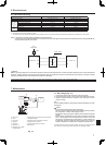
Pipe length :
7 m maximum
No gas charge is needed.
Pipe length exceeding 7 m
Charge the prescribed
amount of gas.
Remove the gage manifold valve quickly from the service port of the stop valve.
After refrigerant pipes are connected and evacuated, fully open all stop valves on
gas and liquid pipe sides.
Operating without fully opening lowers the performance and causes trouble.
Tighten the cap to the service port to obtain the initial status.
Retighten the cap.
Leak test