


4
/
2
10
3 4
90°
2
1
0
/
0
/
/
0
3
0
1
2
1
A
5. Refrigerant piping work
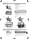
Fig. 5-2
Fig. 5-1
Fig. 5-3
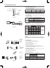
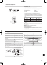
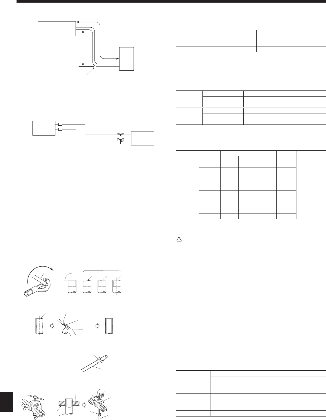
5.1. Refrigerant pipe (Fig. 5-1)
► Check that the difference between the heights of the indoor and outdoor
units, the length of refrigerant pipe, and the number of bends in the pipe
are within the limits shown below.
Models
(A) Pipe length
(one way)
(B) Height
difference
(C) Number of
bends (one way)
SUZ-KA25/KA35 Max. 20 m Max. 12 m
Max. of 10
SUZ-KA50/KA60/KA71 Max. 30 m Max. 30 m *(15 m) Max. of 10
*( ): MFZ
• Height difference limitations are binding regardless of which unit, indoor or out
-
door, is positioned higher.
• Refrigerant adjustment ... If pipe length exceeds 7 m, additional refrigerant
(R410A) charge is required.
(The outdoor unit is charged with refrigerant for pipe length up to 7 m.)
Pipe length
Up to 7 m No additional charge is required.
Exceeding 7 m
Additional charge is required.
(Refer to the table below.)
Refrigerant
to be added
SUZ-KA25/KA35 type
30 g × (refrigerant piping length (m) -5)
SUZ-KA50/KA60 type 20 g × (refrigerant piping length (m) -7)
SUZ-KA71 type 55 g × (refrigerant piping length (m) -7)
Piping preparation
• Refrigerant pipes of 3, 5, 7, 10 and 15 m are available as optional items.
(1)Tablebelowshowsthespecicationsofpipescommerciallyavailable.
Model Pipe
Outside diameter
Min. wall
thickness
Insulation
thickness
Insulation
material
mm inch
SUZ-KA25
For liquid 6.35 1/4 0.8 mm 8 mm
Heat resisting
foam plastic
0.045specic
gravity
For gas 9.52 3/8 0.8 mm 8 mm
SUZ-KA35
For liquid 6.35 1/4 0.8 mm 8 mm
For gas 9.52 3/8 0.8 mm 8 mm
SUZ-KA50
For liquid 6.35 1/4 0.8 mm 8 mm
For gas 12.7 1/2
0.8 mm
8 mm
SUZ-KA60
For liquid 6.35 1/4 0.8 mm 8 mm
For gas 15.88 5/8 0.8 mm 8 mm
SUZ-KA71
For liquid 9.52 3/8 0.8 mm 8 mm
For gas 15.88 5/8 1.0 mm 8 mm
(2) Ensure that the 2 refrigerant pipes are well insulated to prevent condensation.
(3) Refrigerant pipe bending radius must be 100 mm or more.
Caution:
Using careful insulation of specied thickness. Excessive thickness prevents
storage behind the indoor unit and smaller thickness causes dew drippage.
5.2. Flaring work
• Maincauseofgasleakageisdefectinaringwork.
Carryoutcorrectaringworkinthefollowingprocedure.
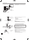
5.2.1. Pipe cutting (Fig. 5-3)
• Using a pipe cutter cut the copper tube correctly.
5.2.2. Burrs removal (Fig. 5-4))
• Completely remove all burrs from the cut cross section of pipe/tube.
• Put the end of the copper tube/pipe to downward direction as you remove burrs
in order to avoid burrs drop in the tubing.
5.2.3. Putting nut on (Fig. 5-5)
• Removearenutsattachedtoindoorandoutdoorunit,thenputthemonpipe/
tube having completed burr removal.
(notpossibletoputthemonafteraringwork)
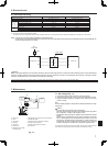
5.2.4. Flaring work (Fig. 5-6)
• Carryoutaringworkusingaringtoolasshownattheright.
Pipe diameter
(mm)
Dimension
A (mm)
B
+0
(mm)
-0.4
When the tool for R410A is used
Clutch type
6.35 0 - 0.5 9.1
9.52
0 - 0.5 13.2
12.7
0 - 0.5 16.6
15.88 0 - 0.5 19.7
Firmly hold copper tube in a die in the dimension shown in the table at above.
(C)
(B)
(A)
ø6.35
ø9.52
ø9.52
ø12.7
ø15.88
Fig. 5-4
Fig. 5-5
Fig. 5-6
A Indoor unit
B Outdoor unit
A Indoor unit
B Outdoor unit
a Copper tubes
b Good
c No good
d Tilted
e Uneven
f Burred
a Burr
b Copper tube/pipe
c Spare reamer
d Pipe cutter
a Flare nut
b Copper tube
a Flaring tool
b Die
c Copper tube
d Flare nut
e Yoke