


Specications are subject to change without notice.
© 2014 Mitsubishi Electric US, Inc.
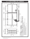
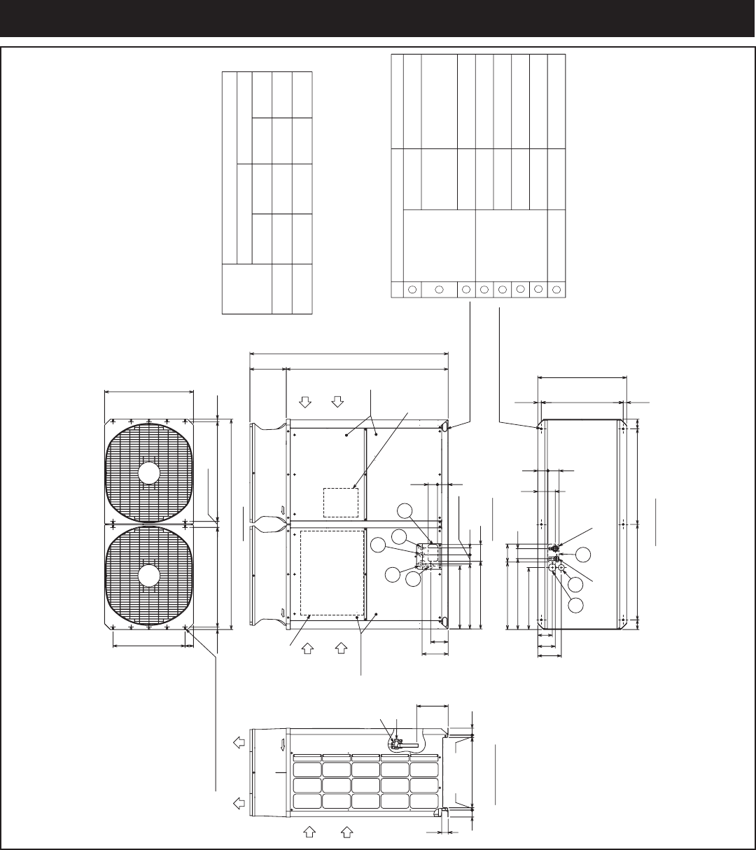
Model: PURY-P120TKMU-A (-BS) – DIMENSIONS
(1-25/32)
(1)
(1)
(1-1/8)
(7/8)
(3/4)
(1-1/8
)(
1-1/8)
(1-1/8)
(5-17/32)(3-1/16)
(5-29/32)(3-23/32)
(2-1/16)
(1-11/32)
(1-3/8)
(7/8)
(2-15/32)
(1-3/4)
(2-9/16)
Fan box
Note 1.Please refer to the engineering manual for information
regarding necessary spacing around the unit and
foundation work. Outdoor unit must be mounted
at least 12" off the ground or 12" above the highest
average snow depth, whichever is greater.
2.At brazing of pipes,wrap the refrigerant service valve
with wet cloth and keep the temperature of
refrigerant service valve under 120°C(248°F).
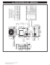
Connecting pipe specifications
(8-9/16)
(5-23/32)
(26-13/16)
(3-5/32)
(3-5/32)
(2-25/32)
(11-15/16)
(4-25/32)
(5-23/32)
(5-3/4)
(3-5/16)
(1-3/16)
(1-3/16)
(3-23/32)
(7-23/32)
(10-11/32)
(3-17/32) (3-1/16)
(23-5/8)
(25/32)
(25/32)
(13/16)
(13/16)
(2-1/4)
(2-1/4)
(3-9/32)
3
1
5
8
4
2
2X2-80(3-5/32)X35(1-13/32) Oval hole
<Sling hole>
6
7
Discharge air
Intake
air
Intake
air
Service
panel
Intake
air
2X3-14(9/16)X20(13/16) Oval hole
(Mounting pitch)
(Mounting pitch)(Mounting pitch)
Control box
Refrigerant service valve
<Low pressure>
Refrigerant service valve
<Low pressure>
Refrigerant service valve
<High pressure>
Refrigerant service valve
<High pressure>
Service panel
2X7-ø4.6(3/16) Hole
(Make hole at the plastic fan guard
for snow hood attachment)
<Snow hood attachment hole>
Front through hole
(Uses when twinning
kit (optional parts)
is mounted.)
ø45 Knockout hole
High
pressure
Low
pressure
High
pressure
Low
pressure
Service valve
*2
*2
*1
*1
Refrigerant pipe
Diameter
ø25.4
ø25.4
ø28.58 Brazed
PURY-P144TKMU
PURY-P120TKMU
ø22.2 Brazed
Model
ø19.05 Brazed
ø28.58 Brazed
ø28.58
ø28.58
ø65 Knockout hole
ø34 Knockout hole
For transmission cables
ø52 Knockout hole
For pipes
Bottom through hole
150 × 94 Knockout hole
140 × 77 Knockout hole
Front through hole
NO.
Usage
For wires
Front through hole
Front through hole
Bottom through hole
Bottom through hole
Front through hole
ø62.7 or ø34.5 Knockout hole
ø43.7 or ø22.2 Knockout hole
Specifications
*1 Expand the on-site piping and connect to the refrigerant service valve piping.ࠉ
*2 Use the pipe joint(field supply) and connect to the refrigerant service valve piping.ࠉ
146
541(21-5/16)
75(2-31/32)
58(2-5/16)
217
145
526(20-23/32)
Front view
Bottom view
Left side view
Top view
262
196
121
303
1347(53-1/16)
1650(64-31/32)
1750(68-29/32)
19.5
831(32-23/32)
831(32-23/32)
19.5
60070
(740)(29-5/32)
29.529.5
562(22-5/32)
740(29-5/32)
7789
80
795(31-5/16)
795(31-5/16)
80
681
140(5-17/32)
49(1-15/16)
54(2-5/32)
57
20
586(23-3/32)
57
20
145
590(23-1/4)
83
150(5-29/32)
561(22-3/32)
516(20-11/32)
8494
PURY-P120,144TKMU-A(-BS)
Unit : mm(in.)
1
2
4
5
6
7
8
3