


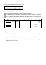
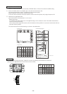
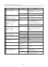
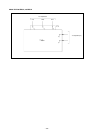
Transmission Power Circuit (30 V) Check Procedure
If “
” is not displayed by the remote control, investigate the points of the trouble by the following procedure and correct it.
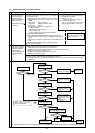
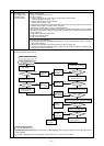
DC24~30 V
Except the above-mentioned
Connector disconnected
Except the above-mentioned
DC24~30 V
Except the above-mentioned
DC24~30 V
Except the above-mentioned
0.5~2.5Ω
Except the above-mentioned
DC280~342 V
Except the above-mentioned
0 Ω
Except the above-mentioned
20~24 Ω
Except the above-
mentioned
refer to "Judging Diode
stack Failure"
Except the above-mentioned
AC187~253 V
Except the above-mentioned
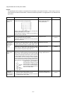
No. Check Item Judgment Response
Disconnect the transmission line from TB3
and check the TB3 voltage.
Check if the following connectors are
disconnected in the outdoor unit’s control
box.
MAIN Board: CNS1, CNVCC3
INV Board: CNVCC2, CNL2, CNDC2
Disconnect the wires from CNVCC3 on the
Main board and check the voltage between
pins 1 and 3 on the wire side of the
CNVCC3.
Tester + .......... 1 pin
Tester - .......... 3 pin
Disconnect the wiring from CNVCC2 on the
INV board and check the voltage between
pins 1 and 3 of CNVCC2.
Tester + .......... 1 pin
Tester - .......... 3 pin
Disconnect the wiring from CNL2 on the
INV board, and check the resistance at
both ends of choke coil L2.
Check the voltage between pins 1 and 3 of
CNDC2 on the INV board.
Check the resistance at both ends of F01
on the G/A board.
Check the resistans at both ends of R1
Chcke the DS
Check the voltage between RS and T on
power supply terminal block TB1.
Check the transmission line for the following, and
correct any defects.
Broken wire, short circuit, grounding, faulty
contact.
to No. 2
Connect the connectors as shown on the electric
wiring diagram plate.
to No. 3
Check the wiring between CNS1 and TB3 for the
following, and correct any defects.
Broken wire, short circuit, grounding, faulty
contact.
If there is no trouble, replace the Main board.
to No. 4
Check the wiring between CNVCC2 and
CNVCC3 for the following, and correct any
defects.
Broken wire, short circuit, grounding, faulty
contact.
to No. 5
to No. 6
Replace choke coil L2.
Replace the INV board.
to No. 7
to No. 8
Replace F01
to No. 9
Replace R1
to No.10
Replace DS
Check the wiring to TB1 for the following and
correct any defects.
Broken wire, faulty contact.
Check the power supply wiring and base power
supply, and correct any defects.
1
2
3
4
5
6
7
8
9
10
-
53
-