


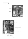
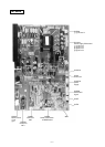
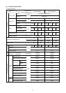
S W U 1 ~ 2
T B 1
Switch unit address set
Terminal block power source
T B 3
T B 7
Terminal block transmisson
GR
Ground terminal
Terminal block transmisson
centralized control
L D 1
S W 1
S W 2 ~4
Switch function selection
Switch display selection self-diagnosis
Luminous diode
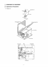
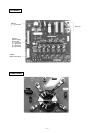
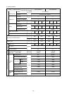
T H 8
bypass outlet temp.
detect at Sub-cool coil
T H H S
Rediator panel temp.detect
6 3 H S
High pressure sensor
S L E V
L E V 1
Electronic expansion valve
(Oil return)
Electronic expansion valve
(Sub-cool coil bypass)
L 2
Choke coil(Transmission)
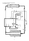
T H 7
liquid outlet temp.
detect at Sub-cool coil
T H 5
T H 2
T H 1
pipe temp.detect
T H 6
OA temp.detect
saturation
evapo.temp.detect
Thermistor
Thermistor
6 3 H
High pressure switch
S V 1 , S V 2
Solenoid valve
(Discharge-suction bypass)
C H 1
Crankcase heater (Compressor)
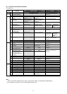
D S A
Surge absorber
Motor Compressor
Motor Fan Heat exchanger
Motor Fan Radiator panel
M F 1
M F
M C
5 2 C
Magnetic contactor
(Inverter main circuit)
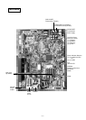
Z N R 1 ~ 4
Varistor
C 1
Capacitor Smoothing
Resistor rush current protect
D C C T
Current Sensor
R 1
R 2
Resistor power regulation
D C L
DC reactor
(Power factor improvement)
I P M
Intelligent Power Module
D S
Diode stack
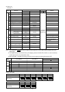
Symbol
Name
Symbol
Name
Symbol
Name
Symbol
Name
discharge pipe temp.detect
4-way valve
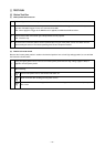
2 1 S 4
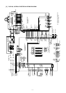
OFF : 0
ON : 1
(at factory shipment)
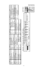
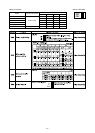
FLAG7
FLAG1
FLAG6
Display
Relay output
display
(Lighting)
During
compressor
run
Crankcase
heater
0000~9999
Display the address and error codes by turns
21S4
SV1 SV2
Check display
(Blinking)
Display at LED lighting (blinking) Remarks SW1 operation
FLAG3 FLAG4FLAG2 FLAG5
FLAG8
FLAG8 always lights at
microcomputer power ON
Always
lighting
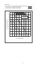
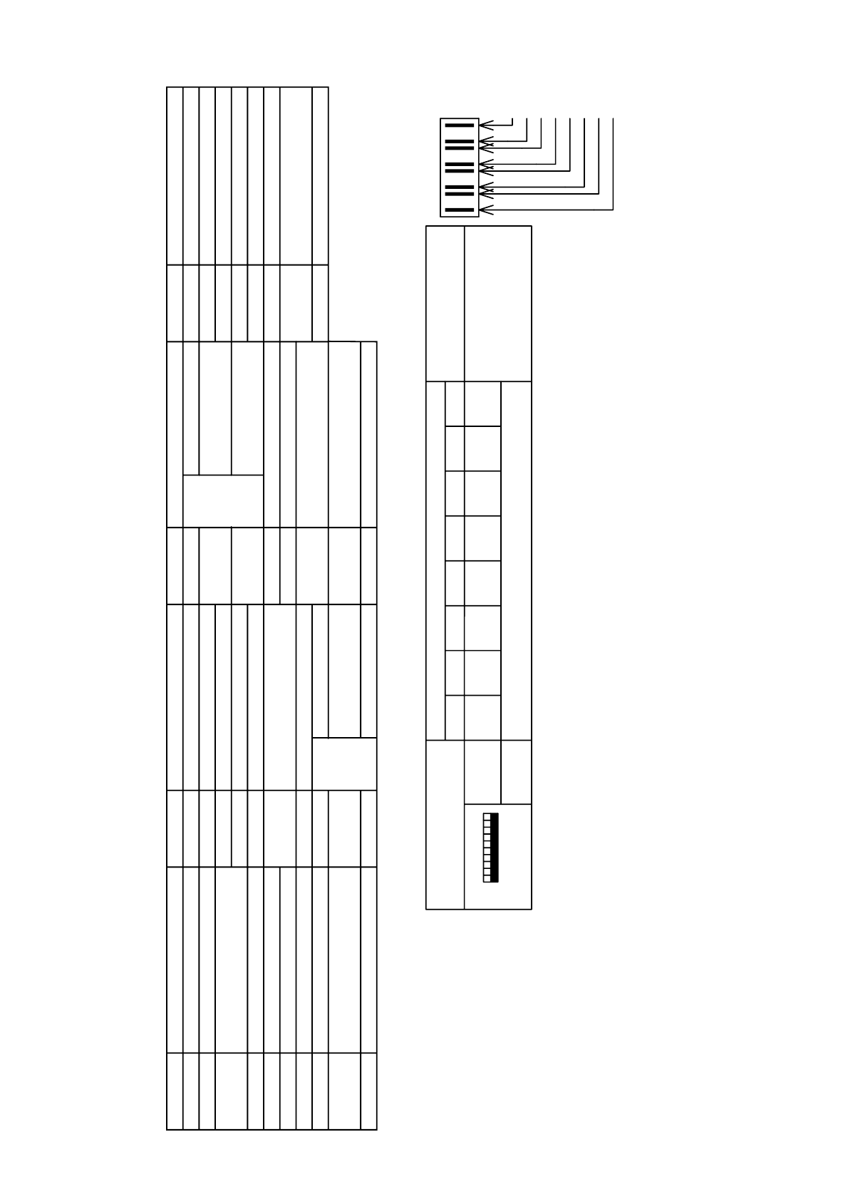
<Operation of self-diagnosis switch (SW1) and LED display>
<LED display>
LD1
FLAG8
FLAG7
FLAG6
FLAG5
FLAG4
FLAG3
FLAG2
FLAG1
1 2 3 4 5 6 7 8 9 10
-
8
-