036-21544-001 Rev. B (1103)
32 Mitsubishi Electronics 2003
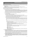
SERVICE PORTS
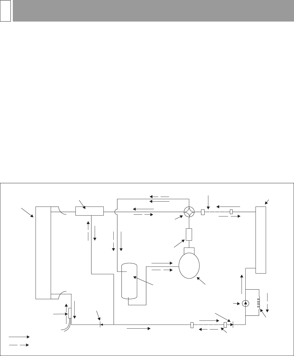
There are two service ports available to service technicians. One port is located at each of the two base valves.
A. Liquid Line Base Valve Service Port. This port is used to evacuate the refrigerant line set when the ball valve is in
the closed position. It may also be used to measure the liquid line pressure or, more accurately, the “saturated line”
pressure during normal operation.
1. During cooling operation this service port is downstream of the metering orifice which is installed inside of the liquid
line base valve body. While in the cooling mode this pressure is typically 25 to 40 PSI above that of the suction
base valve pressure (usually 85 to 110 PSI).
2. During heating operation this pressure continues to be downstream of the capillary tube which is now metering
refrigerant at the outlet of the indoor unit.
B. Suction Base Valve Service Port. This port is also used to evacuate the indoor unit and line set during installation.
The ball valve must be closed to evacuate the line set and indoor unit. During normal cooling mode operation this pres-
sure port indicates evaporator pressure (minus line set pressure drop). Typical cooling mode pressure readings here
are in the range of 55 to 80 PSI during summer operation.
C. Both refrigerant lines must be insulated because the “cooling side” metering device is located in the outdoor
unit. Failure to insulate the liquid line, or more accurately the “saturation line”, will result in condensate dripping from
the line and poor cooling performance.
D. Metering Devices. A fixed orifice that is located in the liquid base valve meters refrigerant in the cooling mode. If a
restriction or a compressor failure occurs this orifice can be easily accessed and cleaned after refrigerant is recovered.
It is important to use a back-up wrench on the liquid line base valve connections when accessing the orifice. Failure to
do so could loosen the base valve connections and cause a refrigerant leak.
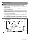
CHARGE COMPENSATOR
(Empty in cooling / full in heating)
FIELD CONNECTED LINE
INDOOR COIL
OUTDOOR
COIL
4-WAY
REVERSING
VALVE
FILTER DRYER
(Solid core)
SUCTION
ACCUMULATOR
LIQUID
SENSOR
COMPRESSOR
FIELD CONNECTED LINE
COOLING CYCLE FLOW
HEATING CYCLE FLOW
CAPILLARY TUBE
(HEATING)
FLOW RATER
(PUGH024 ONLY)
RESTRICTOR
VALVE
FLOW RATER
COOLING
REFRIGERANT SYSTEM13


