


29
OPERATING PROCEDURE PHOTOS&ILLUSTRATIONS
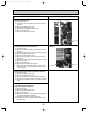
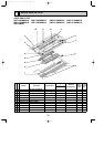
5. Removing the drain pump
(1) Remove the panel.
(2) Unhook the claw in the middle of nozzle and remove the
drain pan.
(3) Remove the address board cover.
(4) Remove the electrical parts cover.
(5) Disconnect the connector of drain pump.
(6) Remove the drain hose.
(7) Remove the drain pump.(2 screws)
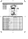
6. Removing the fan motor and line flow fan
(1) Remove the panel.
(2) Unhook the claw in the middle of nozzle and remove the
drain pan.
(3) Unscrew 2 screws at the nozzle side of the heat exchanger.
(4) Remove the address board cover.
(5) Remove the electrical parts cover.
(6) Disconnect the connector of vane motor, fan motor and
drain pump.
(7) Remove the nozzle side of the heat exchanger.(2 screws)
(8) Remove the nozzle.
(9) Remove the drain pump.
(10) Unscrew 2 screws in the motor support.
(11) Remove the fan motor and line flow fan. (The fan motor
and line flow fan can be removed without removing the
heat exchanger.)
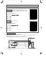
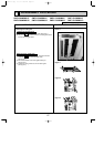
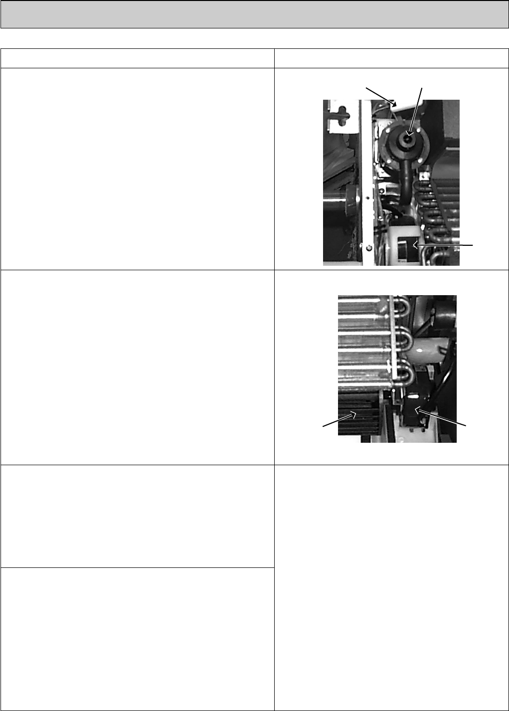
Photo 6
Drain pump
Fan motor
Drain sensor
Photo 7
Fan motor
Line flow fan
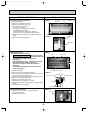
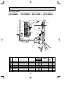
7. Removing the thermistor<Room temperature detection>
(1) Remove the panel.
(2) Remove the address board cover.
(3) Remove the electrical parts cover.
(4) Remove the thermistor. <intake temperature detector>
(5) Disconnect the lead wire from the cord clamp. (5 points)
(6) Disconnect the connector (CN20) on the indoor controller
board.
8. Removing the thermistor
<Liquid pipe temperature detection>
<Gas pipe temperature detection>
(1) Remove the panel.
(2) Remove the address board cover.
(3) Remove the electrical parts cover.
(4) Remove the drain pan.
(5) Remove the thermistor <Gas pipe temperature detection>
/<Liquid pipe temperature detection>.
(6) Disconnect the lead wire from the cord clamp.
(7) Disconnect the connector (CN21)/(CN29) on the indoor
controller board.
OC341B--1.qxp 07.7.11 1:29 PM Page 29