


28
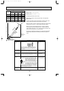
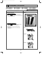
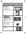
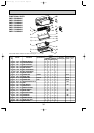
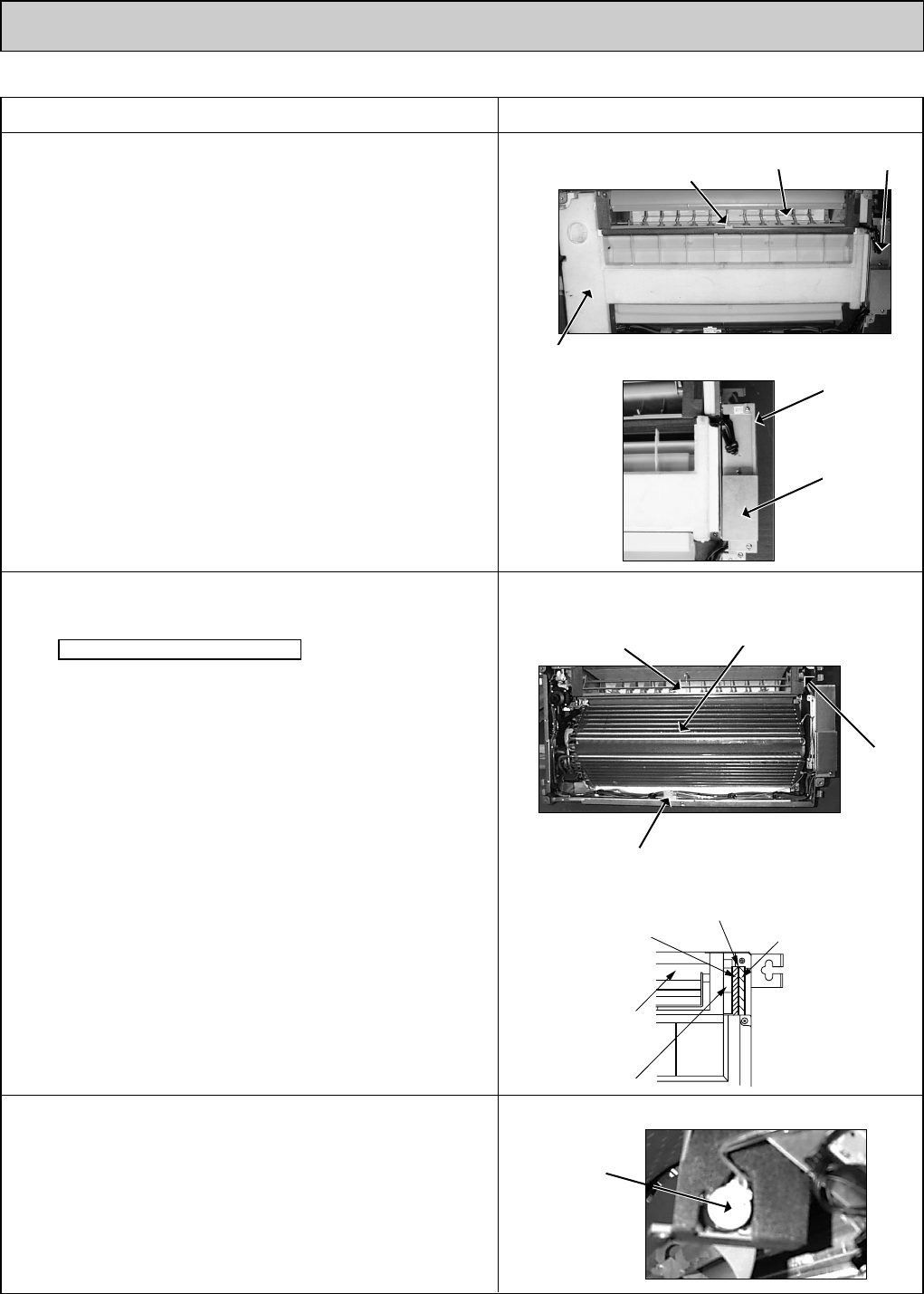
3. Removing the nozzle
Note when the nozzle is removed.
· The insulation material (white) which prevents water
drop is mounted to the side of vane motor. Remove the
insulation material before removing nozzle.
(See figure 4)
·After completing the service, re-mount the insulation
material as before as shown in right figure.
·After service, mount the double layer insulation
without fail.
The hard material side should be faced toward the
nozzle. (See figure 4)
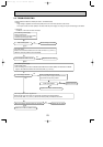
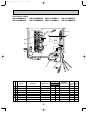
(1) Remove the panel.
(2) Remove the room temperature thermistor.
(3) Unhook the claws in the middle of nozzle and remove the
drain pan. (5 screws) (See photo 2)
(4) Remove the nozzle side of the heat exchanger.(2 screws)
(5) Remove the address board cover.
(6) Remove the electrical parts cover.
(7) Disconnect the connector of vane motor.
(8) Remove the insulation material (white) on the right side of
nozzle.
(9)Remove the nozzle. (6 screws)
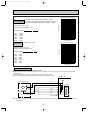
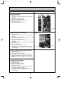
OPERATING PROCEDURE PHOTOS&ILLUSTRATIONS
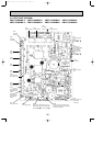
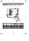
2. Removing the electrical parts box
(1) Remove the panel.
(2) Remove the address board cover.
(3) Remove the electrical parts cover.
(4) Disconnect the connectors of
fan motor, vane motor,
drain pump, room temperature thermistor,
pipe temperature thermistor,
condenser/evaporator temperature thermistor,
and drain sensor on the electrical controller board.
(5) Disconnect the lead wire and earth wire from terminal
block.
(6)Remove the electrical parts box.
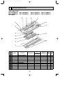
4. Removing the vane motor
(1) Remove the nozzle. Refer to above-mentioned 3
Removing the nozzle.
(2) Remove the vane motor.
Photo 5
Photo 4
Photo 3
Photo 2
Vane motor
Nozzle
Vane motor
Nozzle
Drain pan
Hard side of insulation
Insulation material
Electrical parts
Soft side of insulation
Room temperature thermistor
Nozzle
Claw in middle
of nozzle
Electrical parts
cover
Figure 4
Heat exchanger
Address board
cover
Vane motor
OC341B--1.qxp 07.7.11 1:29 PM Page 28