


20
9
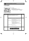
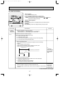
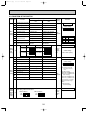
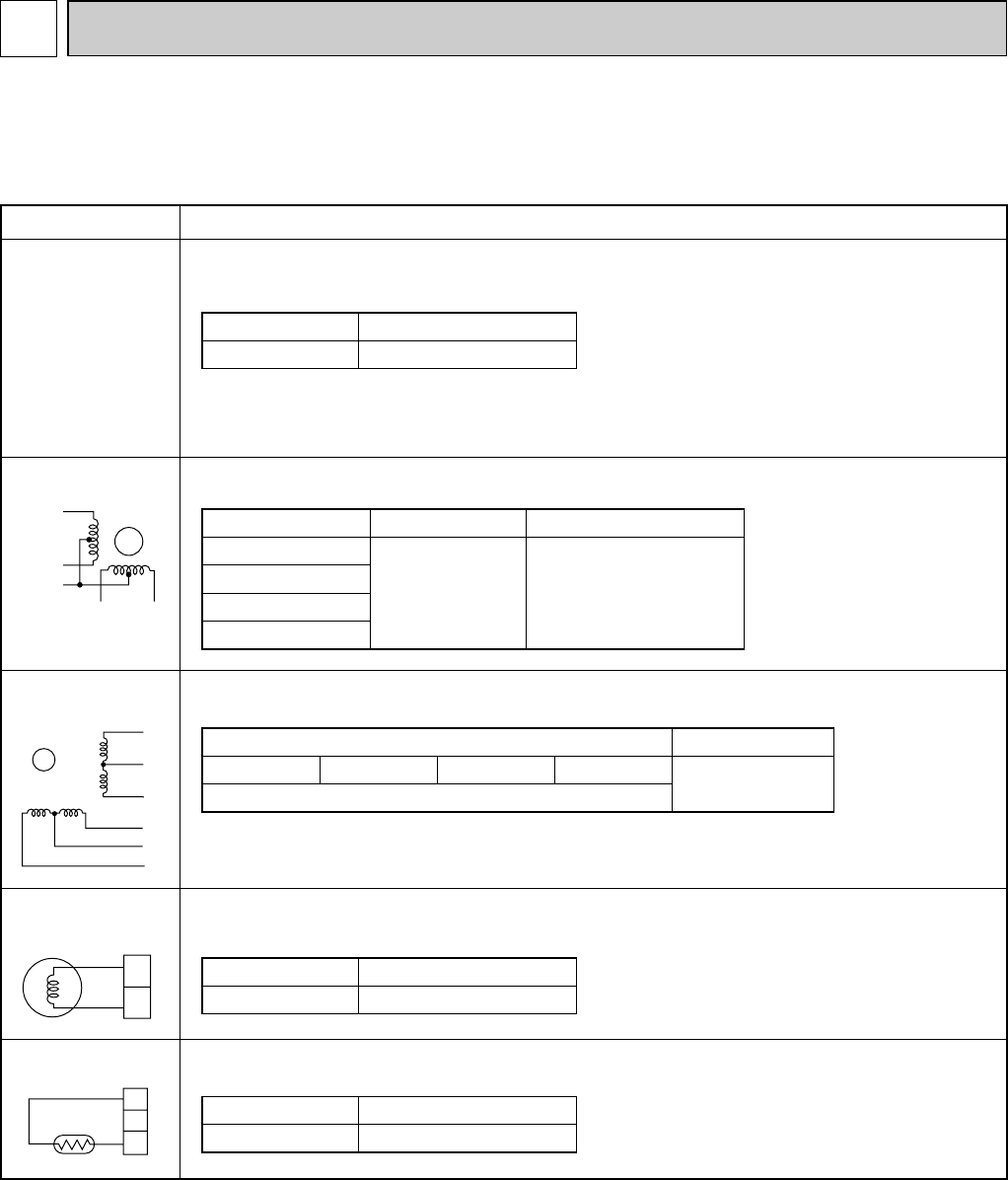
TROUBLE SHOOTING
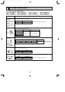
9-1. HOW TO CHECK THE PARTS
PMFY-P06NBMU-E PMFY-P08NBMU-E PMFY-P12NBMU-E PMFY-P15NBMU-E
PMFY-P06NBMU-E1 PMFY-P08NBMU-E1 PMFY-P12NBMU-E1 PMFY-P15NBMU-E1
Parts name Check points
Disconnect the connector then measure the resistance with a tester.
(At the ambient temperature 50°F~86°F)
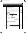
Disconnect the connector then measure the resistance with a tester.
Measure the resistance between the terminals with a tester.
(At the ambient temperature 68°F~86°F)
Measure the resistance between the terminals with a tester.
(At the ambient temperature 68°F)
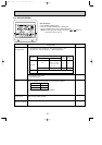
Measure the resistance after 3 minutes have passed since the power supply was turned off.
(At the ambient temperature 32°F~140°F
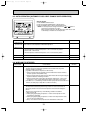
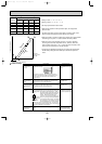
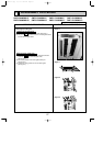
Vane motor (MV)
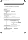
Linear expansion
valve (LEV)
Drain pump (DP)
Drain sensor (DS)
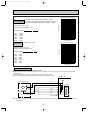
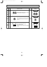
Refer to the next page for the details.
Refer to the next page for the details.
Refer to the next
page for the details.
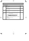
Thermistor (TH21)
<Room temperature
detection>
Thermistor (TH22)
<Liquid pipe temperature
detection>
Thermistor (TH23)
<Gas pipe temperature
detection>
1
2
Blue
Blue
1
2
3
Normal
4.3k"~9.6k"
Abnormal
Open or short
Abnormal
Open or short
Normal
0.6k"~6.0k"
Abnormal
Open or short
Normal
150k" i10%
White-Red Yellow-Brown Orange-Red Blue-Brown
NormalConnector Abnormal
380" i7% Open or short
Normal Abnormal
400"~480" Open or short
Brown — Yellow
Brown — Red
Brown — Orange
Brown — Green
Orange
Red
White
Blue
Brown
Yellow
3
6
15
4
2
MV
M
Orange
Red
Brown
Green
Yellow
31
5
4
2
OC341B--1.qxp 07.7.11 1:29 PM Page 20