


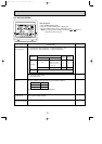

6
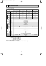
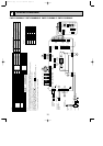
4-2. ELECTRICAL PARTS SPECIFICATIONS
Parts name
Service Ref.
Symbol
TH21
TH22
TH23
FUSE
MF
MV
DP
DS
LEV
TB2
TB5
TB15
Resistance 30˚F/15.8k", 50˚F/9.6k", 70˚F/6.0k", 80˚F/4.8k", 90˚F/3.9k", 100˚F/3.2k"
Resistance 30˚F/15.8k", 50˚F/9.6k", 70˚F/6.0k", 80˚F/4.8k", 90˚F/3.9k", 100˚F/3.2k"
Resistance 30˚F/15.8k", 50˚F/9.6k", 70˚F/6.0k", 80˚F/4.8k", 90˚F/3.9k", 100˚F/3.2k"
250V 6A
Thermistor resistance 30_F/6.3k", 50_F/3.9k", 70_F/2.5k", 80_F/2.0k", 90_F/1.6k", 100_F/1.3k"
(L1, L2, GR) Rated to 330V 30A
(M1, M2, S) Rated to 250V 20A
(1,2) Rated to 250V 10A
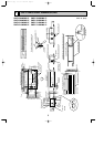
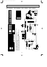
Liquid pipe thermistor
Gas pipe thermistor
Drain pump
Drain sensor
Linear expansion valve
PMFY-P06NBMU-E
PMFY-P06NBMU-E1
PMFY-P08NBMU-E
PMFY-P08NBMU-E
1
PMFY-P12NBMU-E
PMFY-P12NBMU-E
1
PMFY-P15NBMU-E
PMFY-P15NBMU-E
1
Room temperature
thermistor
Fuse
(Indoor controller board)
Fan motor
Vane motor
Power supply
terminal block
Transmission
terminal block
DC Brushless Motor
8-pole OUTPUT 28W
PN0H28-MB
MSFJC 20M23
12V/380
"
PJV-1063
208-240V 50/60Hz
DC12V Stepping motor drive
port dimension [
3.2
(0~2000pulse)
EDM-40YGME
MA-remote controller
terminal block
w
Note : Refer to WIRING DIAGRAM for the supplied voltage.
w
w
w
OC341B--1.qxp 07.7.11 1:29 PM Page 6