


26
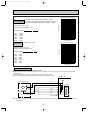
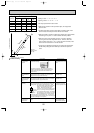
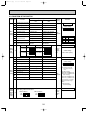
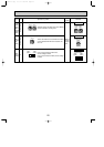
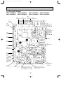
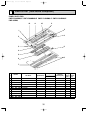
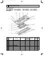
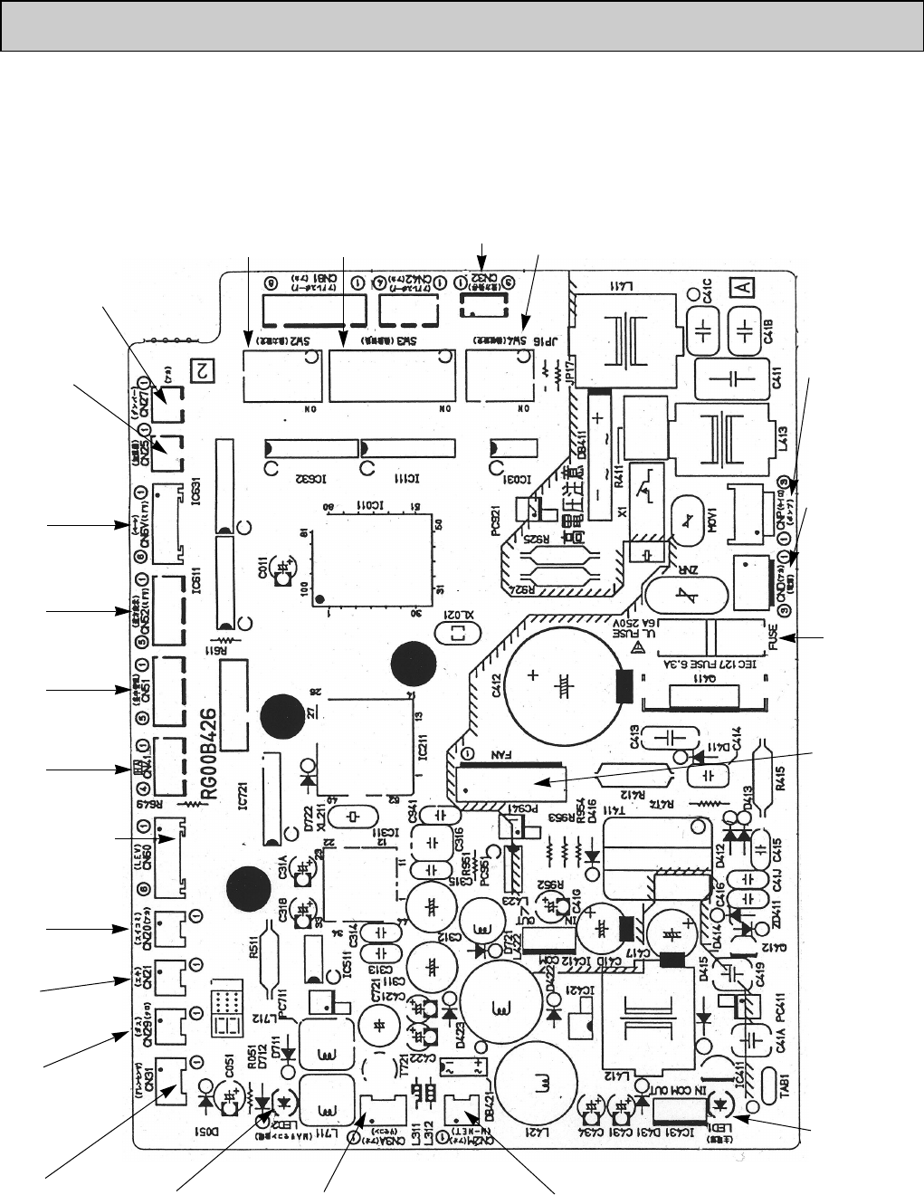
9-4. TEST POINT DIAGRAM
PMFY-P06NBMU-E PMFY-P08NBMU-E PMFY-P12NBMU-E PMFY-P15NBMU-E
PMFY-P06NBMU-E1 PMFY-P08NBMU-E1 PMFY-P12NBMU-E1 PMFY-P15NBMU-E1
LED1
Power supply (I.B)
(Indoor unit :
208-230V)
CNP
Drain pump output
(DP)
Between
11
to
33
208-230V AC
FUSE
6.3A 250V
FAN
Fan motor output
(MF)
CN2M
Connect to the terminal block (TB5)
(M-NET transmission connecting wire)
24-30V DC (non-polar)
CN3A
Connect to the terminal block (TB15)
(MA-Remote controller connecting wire)
Between
11
to
33
8.7-13V DC (Pin
11
(+))
CN29
Pipe temperature
thermistor/Gas
(TH23)
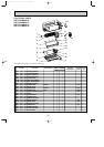
CN60
Linear expansion
valve output (LEV)
CN31
Drain sensor (DS)
CN51
Centrally control
SW2
Capacity setting
CN52
Remote indication
CN6V
Vane motor output
(MV)
CN20
Room temperature
thermistor (TH21)
CN25
Connecter
(Humidifier)
CN27
Connector
(Damper)
SW3
Function setting
CN32
Connector
(Remote switch)
SW4
Model selection
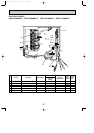
CND
Connect to the
terminal block (TB2)
(Power supply for
indoor controller
board connecting
wire)
Between
11
to
33
208-230V AC
LED2
Power supply (R.B)
CN21
Pipe temperature
thermistor/Liquid
(TH22)
CN41
HA terminal-A
OC341B--1.qxp 07.7.11 1:29 PM Page 26