


5
B
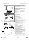
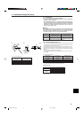
90° ±0.5°
øA
R1/64 to R1/32
A
45°±2°
4. Installing the refrigerant piping
4.1. Precautions
4.1.1. For devices that use R410A refrigerant
• Use ester oil, ether oil, alkylbenzene oil (small amount) as the refrigeration
oil applied to the flared sections.
• Use C1220 copper phosphorus, for copper and copper alloy seamless pipes,
to connect the refrigerant pipes. Use refrigerant pipes with the thicknesses
specified in the table to the below. Make sure the insides of the pipes are
clean and do not contain any harmful contaminants such as sulfuric com-
pounds, oxidants, debris, or dust.
Warning:
When installing or moving the air conditioner, use only the specified refriger-
ant (R410A) to charge the refrigerant lines. Do not mix it with any other refriger-
ant and do not allow air to remain in the lines. Air enclosed in the lines can
cause pressure peaks resulting in a rupture and other hazards.
A12, A18 A24, A30, A36, A42
Liquid pipe
ø6.35 mm, ø1/4 inch ø9.52 mm, ø3/8 inch
thickness 0.8 mm, 1/32 inch thickness 0.8 mm, 1/32 inch
Gas pipe
ø12.7 mm, ø1/2 inch ø15.88 mm, ø5/8 inch
thickness 0.8 mm, 1/32 inch thickness 1.0 mm, 3/64 inch
• Do not use pipes thinner than those specified above.
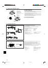
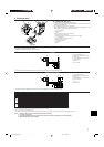
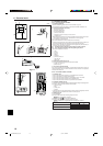
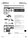
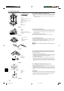
4.2. Connecting pipes (Fig. 4-1)
• When commercially available copper pipes are used, wrap liquid and gas pipes
with commercially available insulation materials (heat-resistant to 100 °C, 212 °F or
more, thickness of 12 mm, 1/2 inch or more).
• The indoor parts of the drain pipe should be wrapped with polyethylene foam insu-
lation materials (specific gravity of 0.03, thickness of 9 mm, 23/64 inch or more).
• Apply thin layer of refrigerant oil to pipe and joint seating surface before tightening
flare nut.
• Use two wrenches to tighten piping connections.
• Use refrigerant piping insulation provided to insulate indoor unit connections. Insu-
late carefully.
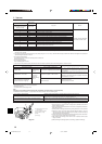
B Flare nut tightening torque
Copper pipe O.D. Flare nut O.D. Tightening torque
(mm, inch) (mm, inch) (N·m, ft·lbs)
ø6.35, 1/4” 17, 43/64 14 - 18, 10 -13
ø9.52, 3/8” 22
, 7/8
34 - 42
, 25 - 30
ø12.7, 1/2” 26
, 1-3/64
49 - 61
, 35 - 44
ø15.88, 5/8” 29
, 1-9/64
68 - 82
, 49 - 59
C Apply refrigerating machine oil over the entire flare seat surface.
D Use correct flare nuts meeting the pipe size of the outdoor unit.
Available pipe size
A12, A18
A24, A30,
A36, A42
Liquid side
ø6.35 –
–ø9.52
ø12.7 –
Gas side –ø15.88
––
? : Factory flare nut attachment to the heat-exchanger.
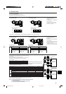
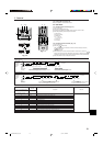
A Flare cutting dimensions
Copper pipe O.D. Flare dimensions
(mm, inch) øA dimensions (mm, inch)
ø6.35, 1/4” 8.7 - 9.1, 11/32 - 23/64
ø9.52, 3/8” 12.8 - 13.2, 1/2 - 33/64
ø12.7, 1/2” 16.2 - 16.6, 41/64 - 21/32
ø15.88, 5/8” 19.3 - 19.7, 49/64 - 25/32
C
D
Fig. 4-1
(inch)
BG79U795H01_en.pm6 05.12.1, 9:48 AM5