


14
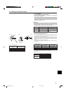
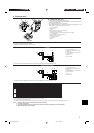
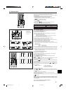
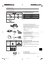
• On wireless remote controller
The continuous buzzer sounds from receiving section of indoor unit.
Blink of operation lamp
• On wired remote controller
Check code displayed in the LCD.
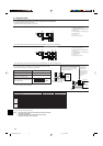
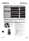
• If the unit cannot be operated properly after the above test run has been performed, refer to the following table to remove the cause.
Symptom
Cause
Wired remote controller LED 1, 2 (PCB in outdoor unit)
PLEASE WAIT
PLEASE WAIT → Error code
Display messages do not appear even
when operation switch is turned ON
(operation lamp does not light up).
For about 2
minutes following
power-on
After about 2
minutes has
expired following
power-on
After LED 1, 2 are lighted, LED 2 is turned off,
then only LED 1 is lighted. (Correct operation)
Only LED 1 is lighted. → LED 1, 2 blink.
Only LED 1 is lighted. → LED 1 blinks twice,
LED 2 blinks once.
• For about 2 minutes following power-on, operation of the
remote controller is not possible due to system start-up. (Cor-
rect operation)
• Connector for the outdoor unit’s protection device is not con-
nected.
• Reverse or open phase wiring for the outdoor unit’s power
terminal block (L1, L2, GR)
• Incorrect wiring between indoor and outdoor units (incorrect
polarity of S1, S2, S3)
• Remote controller wire short
On the wireless remote controller with condition above, following phenomena takes place.
• No signals from the remote controller are accepted.
• OPE lamp is blinking.
• The buzzer makes a short pipng sound.
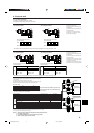
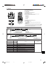
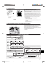
[Output pattern B] Errors detected by unit other than indoor unit (outdoor unit, etc.)
Beeper sounds/OPERATION Symptom Remark
INDICATOR lamp flashes Check code
(Number of times)
1 E9 Indoor/outdoor unit communication error (Transmitting error) (Outdoor unit)
2 UP Compressor overcurrent interruption
3 U3, U4 Open/short of outdoor unit thermistors
4 UF Compressor overcurrent interruption (When compressor locked)
5 U2 Abnormal high discharging temperature/49C worked/insufficient refrigerant
6 U1, Ud Abnormal high pressure (63H worked)/Overheating safeguard operation
7 U5 Abnormal temperature of heat sink
8 U8 Outdoor unit fan safeguard stop
9 U6 Compressor overcurrent interruption/Abnormal of power module
10 U7 Abnormality of super heat due to low discharge temperature
11 U9, UH Abnormality such as overvoltage or voltage shortage and abnormal synchronous
signal to main circuit/Current sensor error
12 ––
13 ––
14 Others Other errors (Refer to the technical manual for the outdoor unit.)
*1 If the beeper does not sound again after the initial two beeps to confirm the self-check start signal was received and the OPERATION INDICATOR lamp does not come on,
there are no error records.
*2 If the beeper sounds three times continuously “beep, beep, beep (0.4 + 0.4 + 0.4 sec.)” after the initial two beeps to confirm the self-check start signal was received, the
specified refrigerant address is incorrect.
For details, check the LED display
of the outdoor controller board.
7. Test run
Note:
Operation is not possible for about 30 seconds after cancellation of function selection. (Correct operation)
For description of each LED (LED1, 2, 3) provided on the indoor controller, refer to the following table.
LED 1 (power for microcomputer) Indicates whether control power is supplied. Make sure that this LED is always lit.
LED 2 (power for remote controller) Indicates whether power is supplied to the remote controller. This LED lights only in the case of the
indoor unit which is connected to the outdoor unit refrigerant address “0”.
LED 3 (communication between indoor and outdoor units only Indicates state of communication between the indoor and outdoor units. Make sure that this LED is
A-control) always blinking.
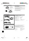
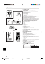
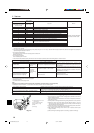
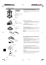
7.4. Check of drainage (Fig. 7-5)
• During the test run, ensure the water is being properly drained out and that no
water is leaking from joints.
• Always check this during installation even if the unit is not required to provide cool-
ing/drying at that time.
• Similarly, check the drainage before finishing ceiling installation in a new premises.
(1) Remove the cover of the water supply inlet and add about 1000 cc, 1/4 gal of
water using a water supply pump etc. During this process, be careful not to spray
water into the drain pump mechanism.
(2) Confirm that water is being drained out through the drainage outlet, after switch-
ing over from remote control mode to test run mode.
(3) After checking the drainage, ensure that the cover is replaced and the power
supply is isolated.
(4) After confirming the drainage system is functioning, replace the drain plug.
A
B
C
D
E
Fig. 7-5
A Insert the pump end 3 to 5 cm,
1-3/16 to 2 inch
B Cover of water supply inlet
C About 1000 cc, 1/4 gal
D Water
E Drain plug
Wireless remote controller
Wired remote
controller
BG79U795H01_en.pm6 05.12.1, 9:48 AM14