


30
SW1
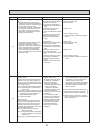
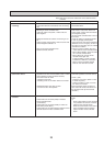
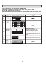
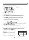
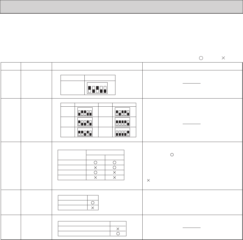
Setting by the dip switch and jumper wire
Functions
Jumper wire
Model
settings
Capacity
settings
Pair number
setting with
wireless
remote
controller
Remarks
SW2
J41
J42
Unit type
setting
JP1
Indoor
controller
board type
setting
JP3
0
1
2
3 ~ 9
Wireless remote
controller setting
Control PCB setting
J41 J42
<Initial setting>
Wireless remote controller: 0
Control PCB: (for both J41 and J42)
Four pair number settings are supported.
The pair number settings of the wireless remote
controller and indoor control PCB (J41/J42) are
given in the table on the left.
(' ' in the table indicates the jumper wire is disco-
nnected.)
There is no jumper (JP1) because these models
have the cond./eva. temperature thermistor (TH5).
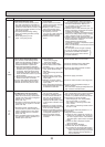
(Marks in the table below) Jumper wire ( : Short : Open)
Without TH5
With TH5
Model
JP1
Product
Service parts
Indoor controller board type
JP3
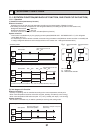
1 2 3 4 5
ON
OFF
MODELS
Service
PLA-A·BA
Service
PLA-A12BA
MODELS
ON
OFF
12345
Service
PLA-A30BA
MODELS
ON
OFF
12345
PLA-A18BA
ON
OFF
12345
PLA-A36BA
ON
OFF
12345
PLA-A24BA
ON
OFF
12345
PLA-A42BA
ON
OFF
12345
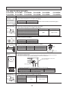
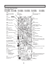
10-8. FUNCTIONS OF DIP SWITCH AND JUMPER WIRE
Each function is controlled by the dip switch and the jumper wire on control P.C. board.
SW1 and SW2 are equipped only for service parts.
Model setting and capacity setting are memorised in the nonvolatile memory of the indoor controller board.