


OC194-41
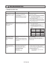
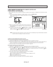
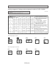
4. How to check the parts PL12FK1/18FK21/24FK21/30FK21/36FK31/42FK21
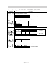
Parts name Check points
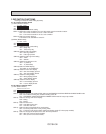
Disconnect the connector then measure the resistance using a tester.
(Surrounding temperature 50-F~86-F)
Measure the resistance between the terminals using a tester.
(Surrounding temperature 68-F~86-F)
Measure the resistance between the terminals using a tester.
(Surrounding temperature 68-F~86-F)
Measure the resistance between the terminals using a tester.
(Surrounding temperature 50-F~86-F)
Vane motor
Drain pump
Drain sensor
(Refer to the thermistor)
(Refer to the thermistor)
Room temperature
thermistor (TH1)
Liquid pipe
thermistor (TH2)
1
2
Yellow
Yellow
1
2
3
Normal
4.3k"~9.6k"
Abnormal
Open or short
Abnormal
Open or short
Normal
0.6k"~6.0k"
NormalConnector Abnormal
300" Open or short
Normal Abnormal
101" Open or short
Orange
Red
White
Red — Yellow
Red — Blue
Red — Orange
Red — White
Blue
Yellow
35
1
2
4
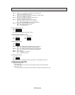
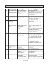
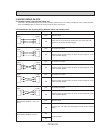
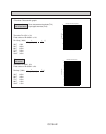
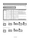
Measure the resistance between the terminals using a tester.
Fan motor
1
1
2
2
3
3
Red
White
Black
Relay connector
Protector
12/18FK
110.9"
132.5"
24FK
101.7"
121.4"
Abnormal
Open or short
30,36FK
122.0"
141.8"
42FK
101.7"
121.4"
Red-Black
White-Black
Motor terminal
or
Relay connector
Normal
PL
M