


3
31/32
0
1/2
1-15/32
2-15/32
3-7/16
4-1/8
5-3/32
6-9/16
8-17/32
9-1/32
10-13/32
11-1/2
12-5/32
12-1/4
2-1/8
23-1/32
18-5/16
17-7/8
17-9/32
16-3/32
15-1/8
14-11/32
12-3/8
4-11/32
2-1/8
0
2-3/8
13/32
13/32
2-3/8
4-11/32
12-3/8
14-11/32
15-1/8
16-3/32
17-9/32
17-7/8
20-3/8
23-1/32
20-7/8
17-9/32
16-15/16
15-1/8
13-11/32
7-7/16
0
8-17/32
13-11/32
R1-15/32
13-3/4
15-1/8
17-9/32
17-11/16
5/8
0
31/32
1-31/32
2-15/16
3-15/16
4-19/32
4-29/32
5-19/32
7-9/16
9-17/32
11
11-1/2
A
B
C
D
F
G
D
E
1/8
1-1/4
1/2
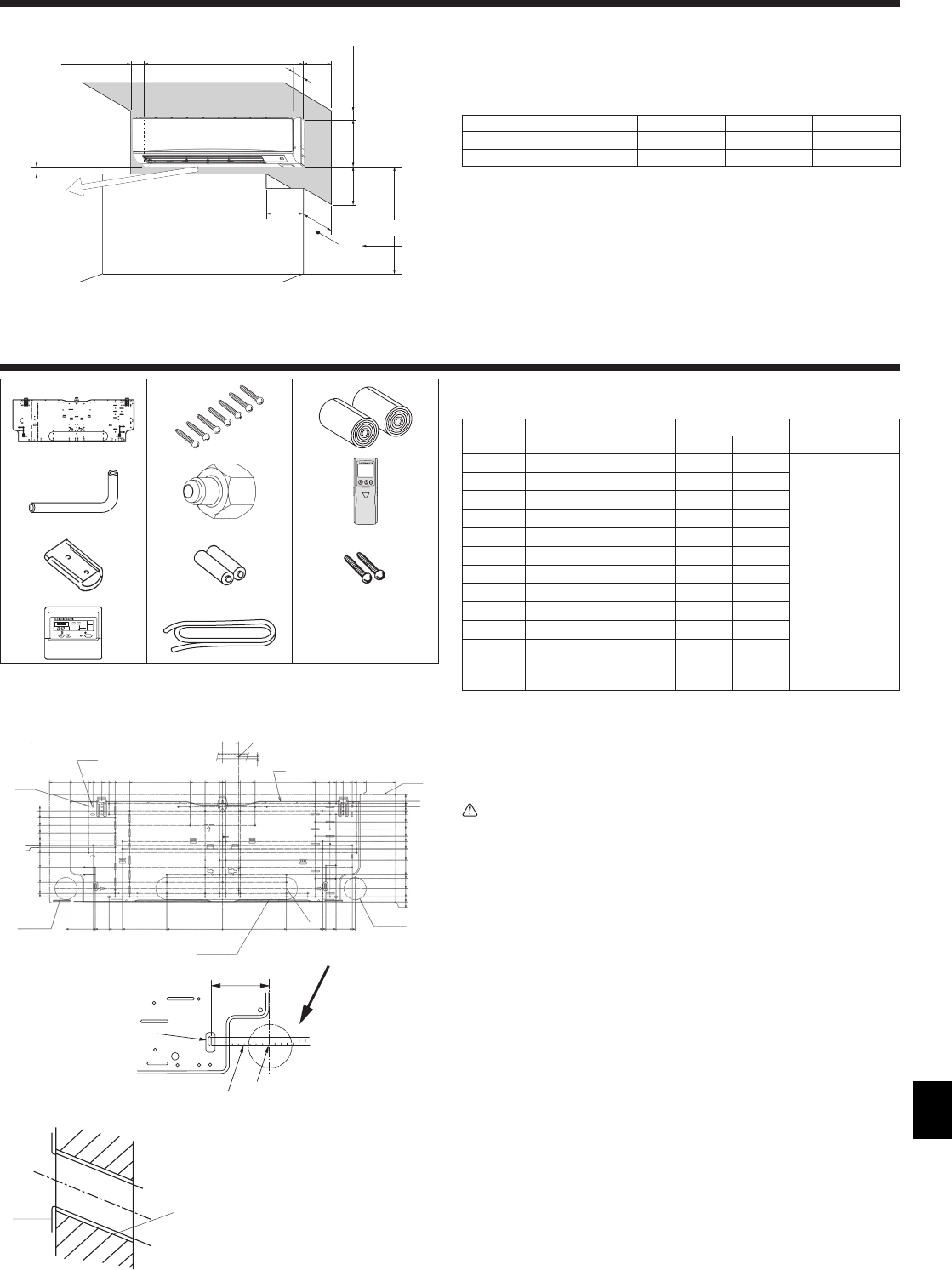
2. Installation location
3. Installing the indoor unit
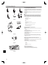
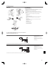
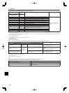
3.1. Check the indoor unit accessories (Fig. 3-1)
The indoor unit should be supplied with the following accessories.
PART
NUMBER
ACCESSORY
QUANTITY
LOCATION OF
SETTING
PKA-A·KAL PKA-A·KA
1
Mount board 1 1
Fix at the back of
the unit
2
Tapping screw 4 × 25
77
3
Felt tape 2 2
4
L-shaped connection pipe 1 1
5
Charge nut 1 1
6
Wireless remote controller 1
7
Remocon holder 1
8
Alkali batteries (size AAA) 2
9
Tapping screw 3.5 × 16 2
0
Wired remote controller 1
a
Remote controller cable 1
b
Spacer 1 1
Make use of
packaging material
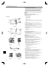
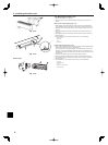
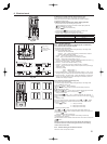
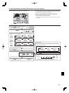
3.2. Installing the wall mounting fixture
3.2.1. Setting the wall mounting fixture and piping positions
(Fig. 3-2)
X Using the wall mounting fixture, determine the unit’s installation position
and the locations of the piping holes to be drilled.
Warning:
Before drilling a hole in the wall, you must consult the building contractor.
PKA-A·KA(L)
A Mount board 1
B Indoor unit
C Bottom left rear pipe hole (ø75-ø80 mm, 2-61/64~3-35/64 inch)
D Bottom right rear pipe hole (ø75-ø80 mm, 2-61/64~3-35/64 inch)
E Knockout hole for left rear hole (75 × 480)
F Bolt hole (4-ø9 mm, 23/64 inch hole)
G Center measurement hole (ø2.5 mm, 3/32 inch hole)
H Tapping hole (75-ø5.1 mm, 13/64 inch hole)
I Hole centre
J Align the scale with the line.
K Insert scale.
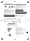
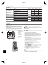
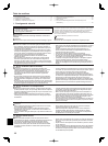
3.2.2. Drilling the piping hole (Fig. 3-3)
X Use a core drill to make a hole of 75-80 mm, 2-61/64~3-5/32 inch diameter
in the wall in the piping direction, at the position shown in the diagram to
the left.
X The hole should incline so that the outside opening is lower than the
inside opening.
X Insert a sleeve (with a 75 mm, 2-61/64 inch diameter and purchased
locally) through the hole.
Note:
The purpose of the hole’s inclination is to promote drain flow.
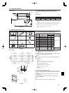
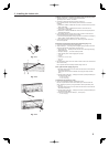
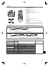
Fig. 2-1
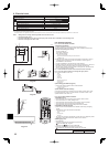
2.1. Outline dimensions (Indoor unit) (Fig. 2-1)
Select a proper position allowing the following clearances for installation and
maintenance.
PKA-A·KA(L)
(mm, inch)
ABCDE
Min. 100.5 Min. 22.4 Min. 48 Min. 250 Min. 220
Min. 3-61/64 Min. 7/8 Min. 1-52/64 Min. 9-27/32 Min. 8-21/32
F Air outlet: Do not place an obstacle within 1500 mm, 59-1/16 inch of the air outlet.
G Floor surface
H Furnishing
I When the projection dimension of a curtain rail or the like from the wall exceeds 60 mm,
2/23/64 inch extra distance should be taken because the fan air current may create a short
cycle.
J 1800 mm,70-7/8 inch or greater from the floor surface (for high location mounting)
K 108 mm, 4-1/4 inch or greater with left or rear left piping.
L Minimum 7 mm, 9/32 inch.
Fig. 3-1
PKA-A·KA(L)
Fig. 3-2
A
K
J
I
3-15/16
(inch)
PKA-A·KA(L)
Fig. 3-3
A
C
D
E
B
A Sleeve
B Hole
C (Indoors)
D Wall
E (Outdoors)
*
G
F
A
B
1170
46-1/16
365
14-3/8
H
E
J
L
I
D
C
295
11-39/64
K
(inch)
1
2 3
4 5 6
7 8 9
0
ON/OFF
TEMP.
a b
–
(mm)