


12
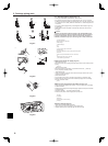
6. Electrical work
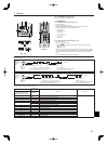
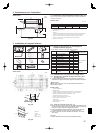
Function table
Select unit number 00
Mode Settings Mode no. Setting no. Initial setting setting
Power failure automatic recovery Not available
01
1
Available *1
2
Indoor temperature detecting Indoor unit operating average
02
1
Set by indoor unit’s remote controller 2
Remote controller’s internal sensor 3
LOSSNAY connectivity Not Supported
03
1
Supported (indoor unit is not equipped with outdoor-air intake) 2
Supported (indoor unit is equipped with outdoor-air intake) 3
Power voltage 230 V
04
1
208 V 2
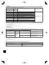
Select unit numbers 01 to 03 or all units (AL [wired remote controller]/07 [wireless remote controller])
Mode Settings Mode no. Setting no. Initial setting setting
Filter sign 100Hr
07
1
2500Hr 2
No filter sign indicator 3
Fan speed Silent
08
1
–
Standard
2
High ceiling 3
–
*1 When the power supply returns, the air conditioner will start 3 minutes later.
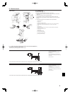
7. Test run
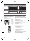
7.1. Before test run
X After completing installation and the wiring and piping of the indoor and
outdoor units, check for refrigerant leakage, looseness in the power
supply or control wiring, wrong polarity, and no disconnection of one
phase in the supply.
X Use a 500-volt megohmmeter to check that the resistance between the
power supply terminals and ground is at least 1.0 MΩ.
X Do not carry out this test on the control wiring (low voltage circuit)
terminals.
Warning:
Do not use the air conditioner if the insulation resistance is less than 1.0 MΩ.
Insulation resistance.
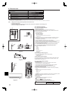
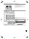
7.2. Test run
The following 3 methods are available.
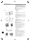
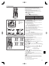
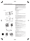
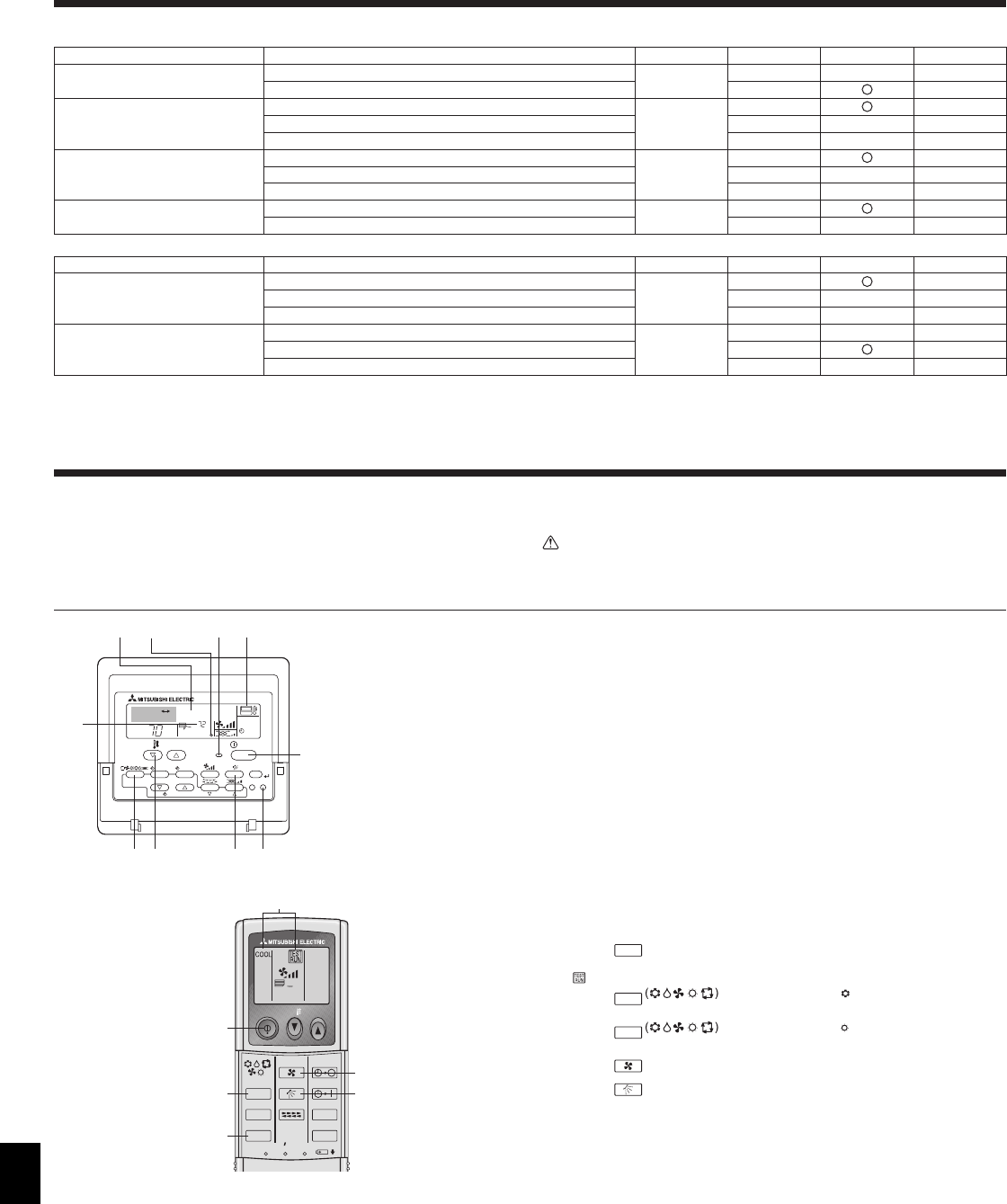
7.2.1. Using wired remote controller (Fig. 7-1)
1 Turn on the power at least 12 hours before the test run.
2 Press the [TEST] button twice. “TEST RUN” liquid crystal display
3 Press the [Mode selection] button. Make sure that wind is blown out.
4 Press the [Mode selection] button and switch to the cooling (or heating) mode.
Make sure that cold (or warm) wind is blown out.
5 Press the [Fan speed] button. Make sure that the wind speed is switched.
6 Check operation of the outdoor unit fan.
7 Release test run by pressing the [ON/OFF] button. Stop
8 Register a telephone number.
The telephone number of the repair shop, sales office, etc., to contact if an
error occurs can be registered in the remote controller. The telephone number
will be displayed when an error occurs. For registration procedures, refer to the
operation manual for the indoor unit.
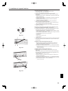
7.2.2. Using wireless remote controller (Fig. 7-2)
1 Turn on the power to the unit at least 12 hours before the test run.
2 Press the
TEST RUN
button twice continuously.
(Start this operation from the status of remote controller display turned off.)
A and current operation mode are displayed.
3 Press the
MODE
button to activate
COOL
mode, then check whether
cool air is blown out from the unit.
4 Press the
MODE
button to activate
HEAT
mode, then check whether
warm air is blown out from the unit.
5 Press the
FAN
button and check whether fan speed changes.
6 Press the
VANE
button and check whether the auto vane operates properly.
7 Press the ON/OFF button to stop the test run.
Note:
• Point the remote controller towards the indoor unit receiver while following
steps 2 to 7.
• It is not possible to run the in FAN, DRY or AUTO mode.
ON/OFF TEMP
FAN
VANE
TEST RUN
AUTO STOP
AUTO START
h
min
LOUVER
MODE
CHECK
RESETSET CLOCK
5
7
A
3,4
2
6
Fig. 7-2
Fig. 7-1
°F
°F
SIMPLE
PAR-21MAA
ON/OFF
FILTER
CHECK
OPERATION
CLEAR
TEST
TEMP.
MENU
BACK DAY
MONITOR/SET
CLOCK
ON/OFF
TEST RUN
COOL, HEAT
A
F
C
EDB
MIHG
A ON/OFF button
B Test run display
C Indoor temperature liquid
line temperature display
D ON/OFF lamp
E Power display
F Error code display
Test run remaining time
display
G Set temperature button
H Mode selection button
I Fan speed button
M TEST button