


24
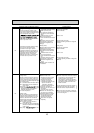
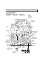
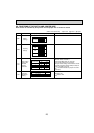
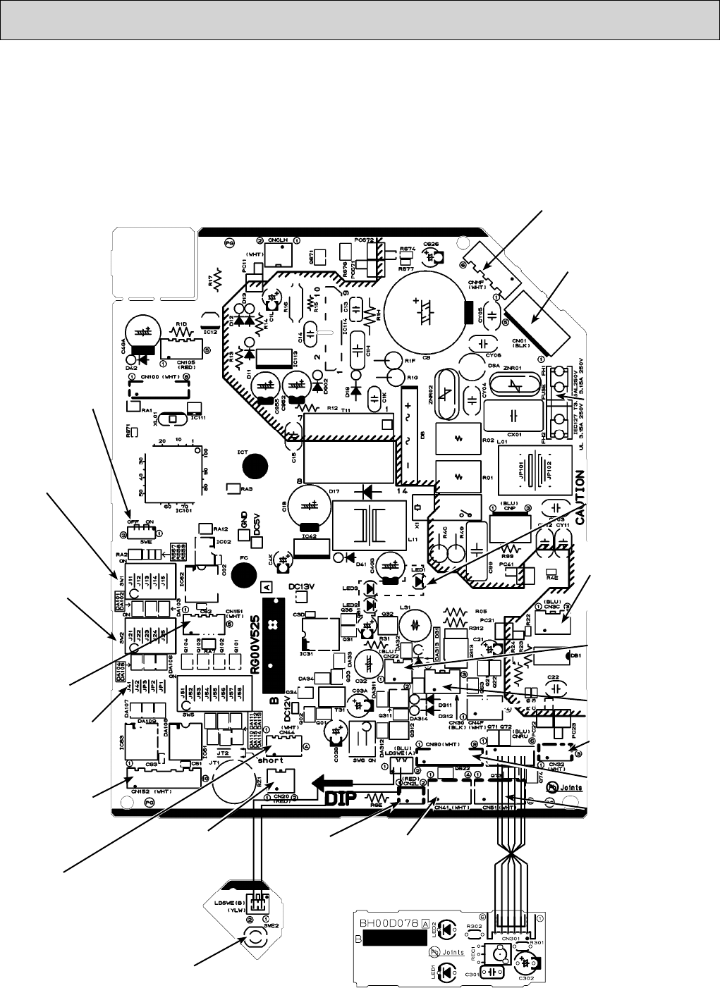
9-7. TEST POINT DIAGRAM
Indoor controller board
PKA-A24KA.TH PKA-A30KA.TH PKA-A36KA.TH
PKA-A24KAL.TH PKA-A30KAL.TH PKA-A36KAL.TH
{
CN51
Centrally control
CN44
Pipe temperature thermistor
1-2 : Liquid (TH2)
3-4 :
Condenser/Evaporator
(TH5)
CN20
Room temp.
thermistor (TH1)
CN90
Connect to the remote
operation adapter
CNMF
Connect to the
fan motor (MF)
1-3 : DC294~325V
4-3 : DC15V
5-3 : DC0~6.5V
6-3 : DC0
or DC15V
FUSE
(3.15A 250V)
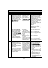
SWE
Emergency
operation connector
SW1
Model selection
SW2
Capacity setting
CN151
Connect to the
vane motor (MV)
Jumper wire J41,J42
Pair No. setting for
wireless remote controller
CN01
Connect to the
Terminal block (TB4)
1-3 : 208/230VAC
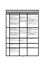
LED1:Power supply (I.B)
LED2:Power supply (R.B)
LED3:Transmission
(Indoor/outdodr)
CN3C
Transmission
(Indoor/outdodr)
(DC 0~24V)
CN30
Connector (LLC)
CN22
Connect to the terminal
block (TB5) (Remote
controller connecting
wire) (only PKA-A·KA)
CN2L
Connector
(LOSSNAY)
SWE2
Emergency
operation switch
CN41
Connector
(HA terminal-A)
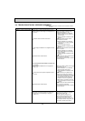
Wireless remote controller board
CN32
Remote switch
CN152
Connector
(Back-up heating)