


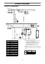
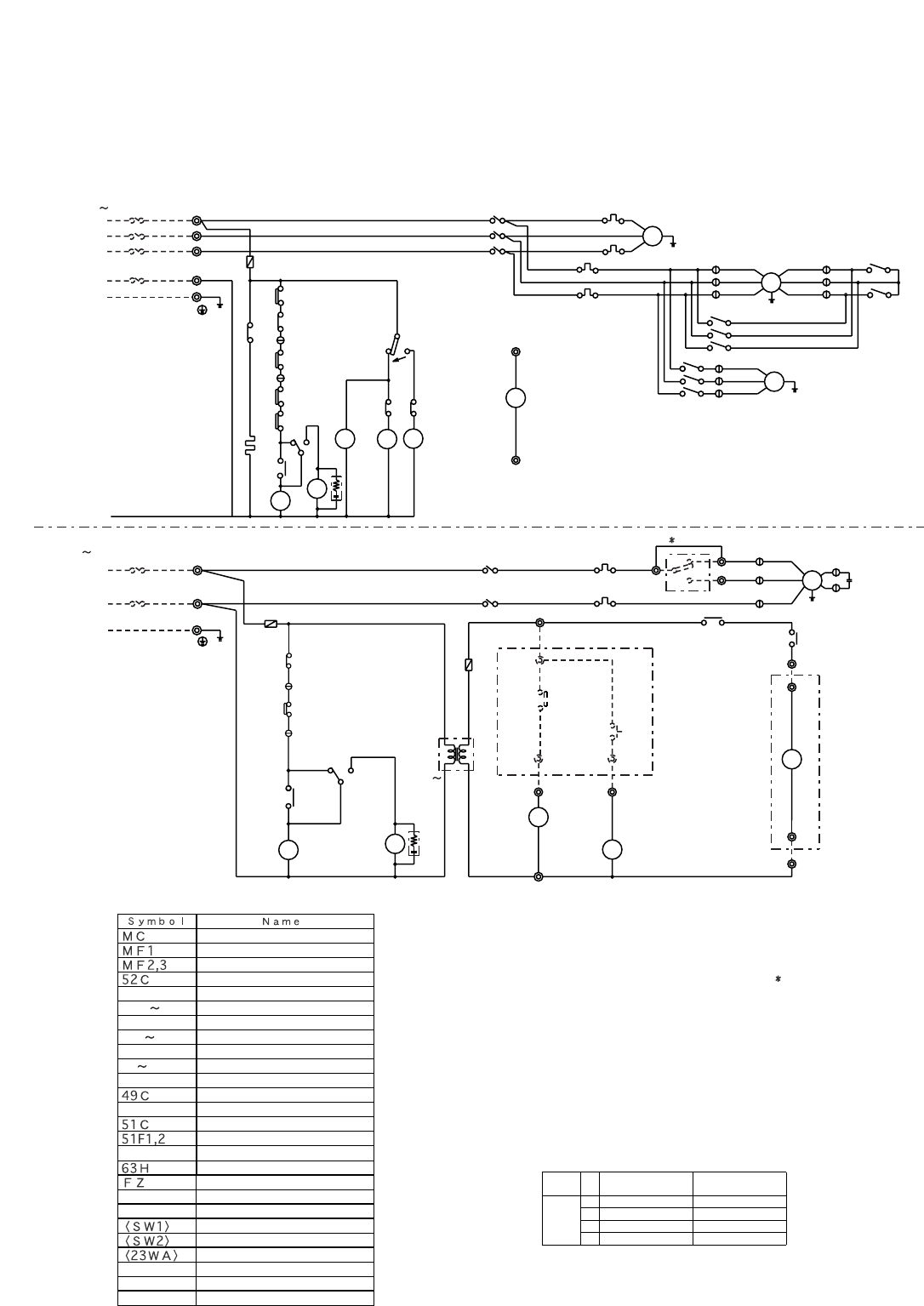
- 56 -
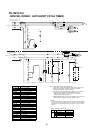
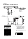
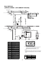
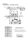
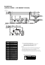
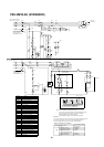
PE-7MYC-EU
(SPECIAL ORDER : LOW AMBIENT COOLING)
Note:1.The dotted lines show field wiring.
2.The figure in the parentheses show field supply parts.
3.Color of earth wire is yellow and green twisting.
4.Not specified color of wire is brown.
5.Please remove the jumper wire ( Mark) in the above
diagram if you use the Switch <SW2> at local.
If the Switch <SW2> is not used, the Fan motor
(indoor) drives at high speed.
6.Specification subject to change without notice.
Caution,
1.To protect each Fan motor and Compressor from abnormal
current, Over current relays <51C>, <51F1,2> are installed.
Therefore, do not change factory set value of Over current
relays.
H
OUTDOOR
5
3
23C
1
1
3
2
C6
5
C4
4
C4
52F3
52F2
BLACK
WHITE
RED
52F4
49F
F2
52
F3
52
52F4
52F2
52F1
52F3
CR1
CR2
GRAY
CH
52F1
FZ
FZ
30
BLUE
30FZ
F3(3.15A)
51C
63H
51F2
CZ2
CZ
30
CZ
30
52C
CZ1
15
CZ2
14
49C
52C
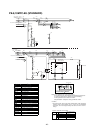
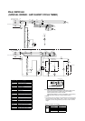
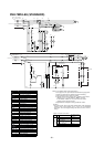
PE-7MYC-EU
PU-7MYC1-EU
PE
GRAY
GRAY
BLUE
BROWN
RED
C1
C1
4
2
1
SW2(FIELD SUPPLY)
JUMPER
TB4
TB4
6
7
5
Low
Hi
C5
C4
15
15
6
5
RED
MC
3
2
1
C
BLACK
WHITE
MF3
Single Phase
220 240Volt,
50Hertz
Power Supply,
3Phase
50Hertz
Power supply,
380 415Volt,
CZ2
14
TB3
52C
14
CIRCUIT BREAKER
(FIELD SUPPLY) 15A
BLUE
(3.15A)
RED
BLUE
RED
TB2
L
N
4
CIRCUIT BREAKER
(FIELD SUPPLY) 100A
51C
3
2
1
51F2
CZ1
WHITE
51F1
MF1
52F1
MF2
RED
RED
WHITE
BLACK
BLACK
BLACK
F2
WHITE
BLACK
WHITE
RED
RED
RED
TB1
L1
L2
L3
N
TB5
(3.15A)
F1
23WA
220
240V
24V
AC
AC
Tr
TB4
TB4
SWITCH BOX
(FIELD SUPPLY)
1
SW1
23
FZ
PE
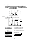
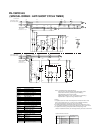
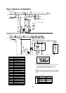
Run capacitor
Connector
(compressor)
Internal thermostat
Internal thermostat(fan O/D)
F1 3
Tr
49F
52F1
23C
CZ1, 2
C
Surge killer
CR1, 2
C1, 3~6
30CZ, FZ
Compressor motor
52F2 4
TB1 5
Over current relay
Fan motor (outdoor)
Contactor (compressor)
Over current relay(fanI/D,O/D)
Contactor (fan I/D)
Contactor (fan O/D)
Ambient temperature
Fuse (3.15A)
CH
Crankcase heater
Terminal block
Fan motor (indoor)
(compressor)
High-pressure switch
Auxiliary relay (fan)
Auxiliary relay (compressor)
Auxiliary relay (check)
Switch (on)
Switch (Fan Hi-Low)
Thermostat (room temp.)
Transformer
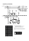
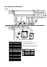
Option controller connection.
24VAC(N)
FAN HI
COMP
24VAC(L)
PAC-204RC (Option)
terminal no.
2
3
Power (Neutral)
Fan operation
Cooling operation
Power (Active)
Function
4
1
No.
TB4
Symbol
Thermostat (freeze protection)26L
3
1
C3
C3
51F1
26L