


- 14 -
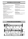
SELECTION PROCEDURE
1. Model Selection (With actual examples)
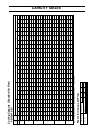
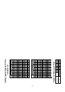
First step, to select the approximate model:
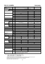
Based on the cooling load and the cooling capacity listed in the capacity table, select the applicable model.
Notes:
*1. The correct WB is required since it has a serious effect on the capacity.
*2. The cooling capacity decreases as the outdoor temperature increases. Therefore, the estimated highest
temperature during an air conditioning time frame is the "designed outdoor temperature". However, it is
recommended that the abnormal outdoor temperature which may occur once or twice a year be excluded from
the calculation to avoid selection of an excessively large capacity model.
*3. The wind pressure loss of an air duct should be calculated correctly. If a value having an excessive allowance
is used, an excessively large model will be selected. Moreover, an excessively high air flow will be induced
during actual operation causing the generation of high operating sounds and carry-over of condensed water.
(Step-1) Confirmation of operation range
Confirm that the conditions given above for the model to be selected are within the
operation range listed on Page 36.
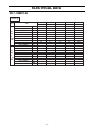
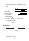
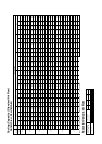
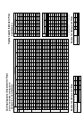
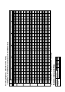
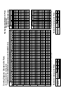
(Step-2) Calculation of actual air flow, external static pressure, and fan motor input
Based on the designed air flow and external static pressure, obtain the actual air flow,
actual external static pressure, and fan motor power input from the fan performance
table for the model selected. For an explanation of how to use the fan performance
table, see the following examples.
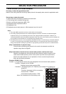
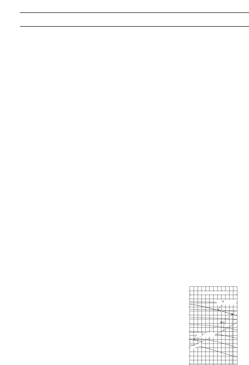
Example: PE-8MYC, 50Hz
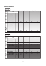
Example 1. (To operate with values near to the designed air flow and external static pressure.)
Condition : Designed air flow 70CMM
Designed external static pressure 60Pa
Calculation : The designed point is A. Therefore, duct resistance line passing A is
dotted line.
Therefore, actual point is B for ∆ connection
Actual air flow = 77CMM
Actual external static pressure = 70Pa
Notes: Duct resustance line is secondary curve.
Second step, to select the model:
To select the model, the following conditions must be known:
(1) Total cooling load or sensible cooling load
(2) Indoor conditioned temperature (WB*1, DB)
(3) Designed outdoor temperature (DB)*2
(4) Designed air flow
(5) Designed external static pressure (= Wind pressure loss of air duct)*3
450
400
350
300
250
200
150
100
50
(Pa)
Fan speed
(rpm)
50 55 60 65 70 75 80
Recommended Range
Internal SP
0
Total static pressure
Air flow (CMM)
800
900
1000
1100
1200
1300
1400
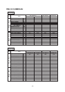
Fan Performance Curve 50Hz
For connection
operation line
For connection
operation line
77
60Pa
A
B